

Bistable molecular mechanical devices with a middle rotating segment activated by an electric field for electronic switching, gating, and memory applications
a molecular mechanical device and rotating segment technology, applied in the field of molecular systems, can solve the problems of slow switching time of molecules, irreversible switches, and large energy expenditure to toggle switches, and achieve the effect of fast switching time, easy and cheap production
- Summary
- Abstract
- Description
- Claims
- Application Information
AI Technical Summary
Benefits of technology
Problems solved by technology
Method used
Image

Examples
example 1a
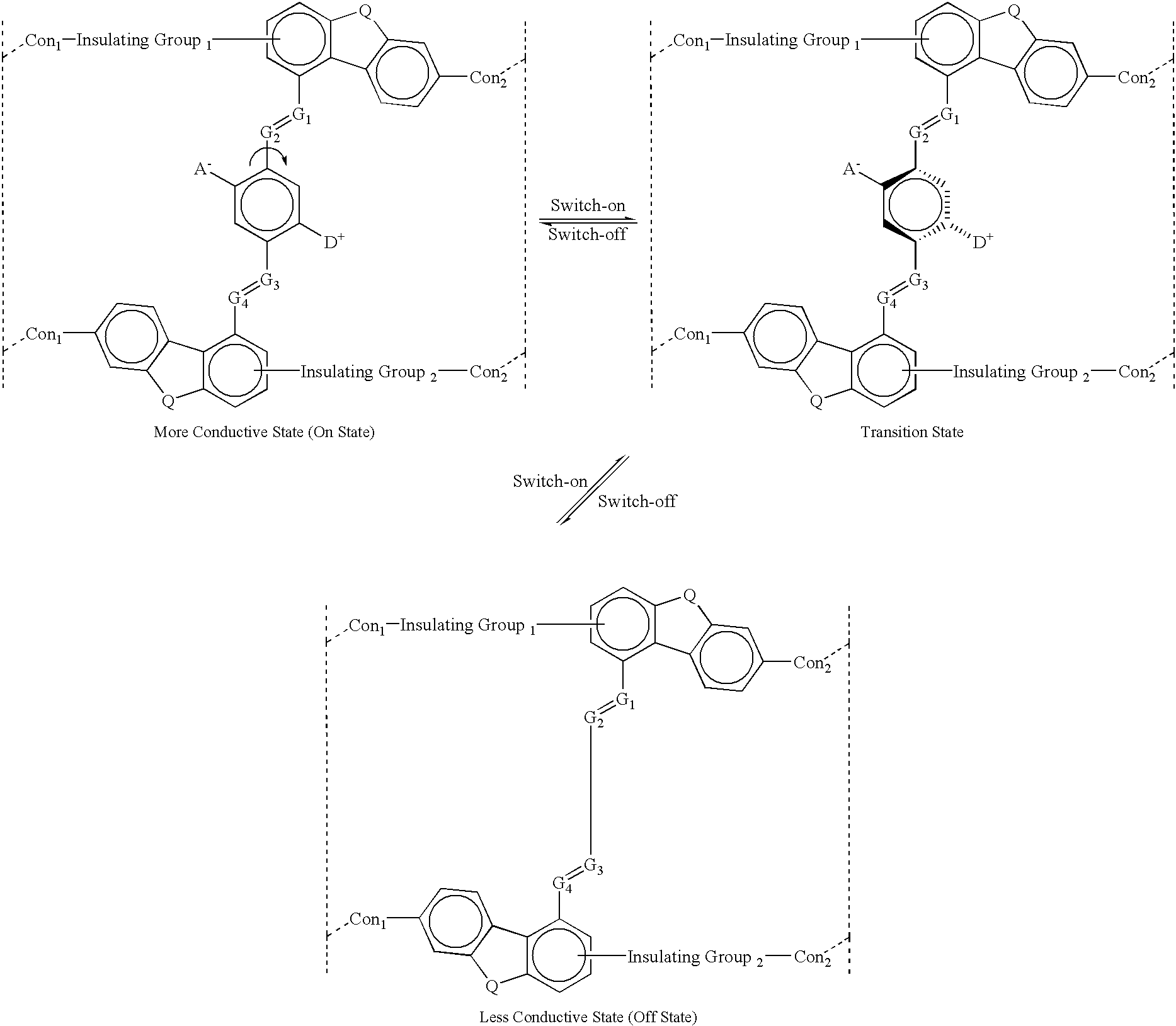
where:
The letter A.sup.- represents an Acceptor group; it is an electron-withdrawing group. It may be one of following: hydrogen, carboxylic acid or its derivatives, sulfuric acid or its derivatives, phosphoric acid or its derivatives, nitro, nitrile, hetero atoms (e.g., N, O, S, P, F, Cl, Br), or functional group with at least one of above-mentioned hetero atoms (e.g., OH, SH, NH, etc.), hydrocarbon (either saturated or unsaturated) or substituted hydrocarbon.
The letter D.sup.+ represents a Donor group; it is an electron-donating group. It may be one of following: hydrogen, amine, OH, SH, ether, hydrocarbon (either saturated or unsaturated), or substituted hydrocarbon or functional group with at least one of hetero atom (e.g., B, Si, N, O, S, P, I). The donor is differentiated from the acceptor by that fact that it is less electronegative, or more electropositive, than the acceptor group on the molecule.
The letters Con.sub.1, and Con.sub.2 represent connecting units between a molec...
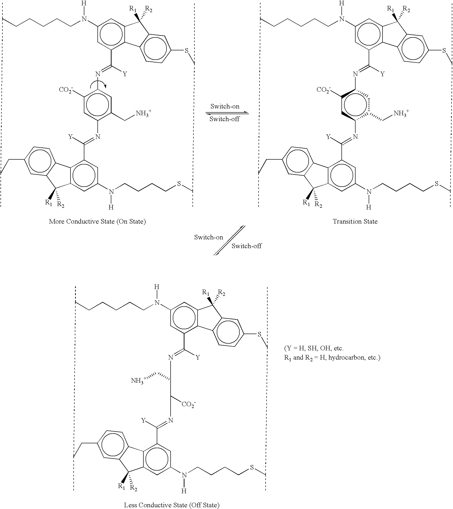
example 1b
The molecule shown above (Example 1b) has been designed with the internal rotor 32 perpendicular to the orientation or current-flow axis of the entire molecule 30. In this case, the external field is applied along the orientation axis of the molecule 30 as pictured--the electrodes (vertical dotted lines) are oriented perpendicular to the plane of the paper and perpendicular to the orientation axis of the molecule 30. Application of an electric field oriented from left to right in the diagrams will cause the rotor 32 as pictured in the upper left diagram to rotate to the position shown on the lower diagram, and vice versa. In this case, the rotor 32 as pictured in the lower diagram is not coplanar with the rest of the molecule, so this is the OFF or low conductivity state of the molecule, whereas the rotor is substantially coplanar with the rest of the molecule on the upper left diagram, so this is the ON or high conductivity state of the molecule. The structure shown in the upper ri...
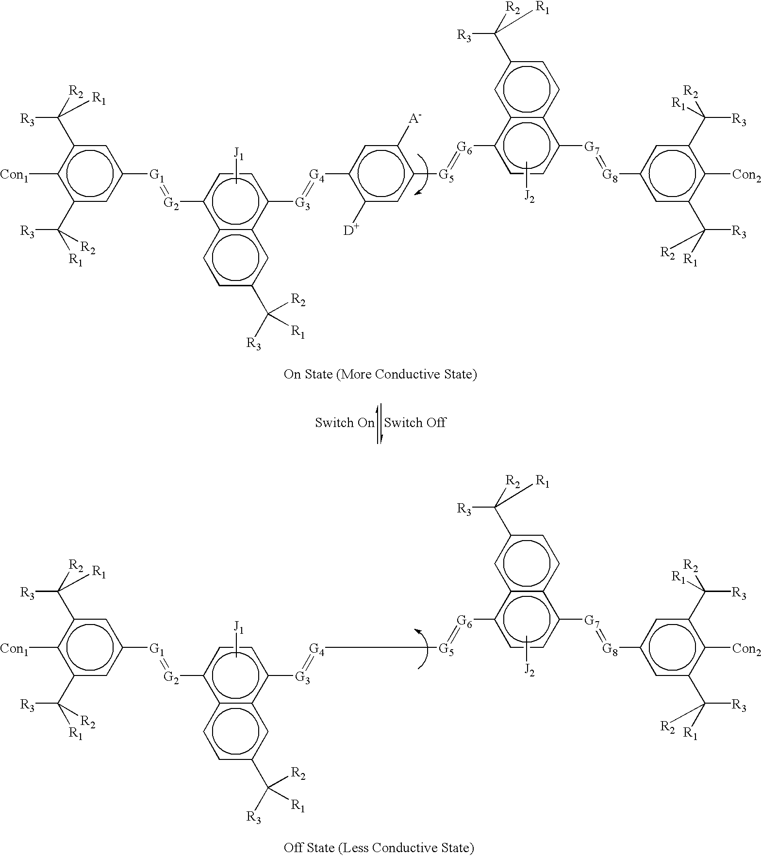
example 2a
where:
The letter A.sup.- represents an Acceptor group; it is an electron-withdrawing group. It may be one of following: hydrogen, carboxylic acid or its derivatives, sulfuric acid or its derivatives, phosphoric acid or its dertives, nitro, nitrile, hetero atoms (e.g., N, O, S. P, F, Cl, Br), or functional group with at least one of above-mentioned hetero atoms (e.g., OH, SH, NH, etc.), hydrocarbon (either saturated or unsaturated) or substituted hydrocarbon.
The letter D.sup.+ represents a Donor group; it is an electron-donating group. It may be one of following: hydrogen, amine, OH, SH, ether, hydrocarbon (either saturated or unsaturated), or substituted hydrocarbon or functional group with at least one of hetero atom (e.g., B, Si, I, N, O, S, P). The donor is differentiated from the acceptor by that fact that it is less electronegative, or more electropositive, than the acceptor group on the molecule.
The letters Con.sub.1, and Con.sub.2 represent connecting units between one molecu...
PUM
| Property | Measurement | Unit |
|---|---|---|
| angle | aaaaa | aaaaa |
| size | aaaaa | aaaaa |
| heights | aaaaa | aaaaa |
Abstract
Description
Claims
Application Information