Electro-optic device with gap-coupled electrode

a gap-coupled electrode and optical device technology, applied in optics, instruments, optical elements, etc., can solve problems such as unsatisfactory polarization rotation, and achieve the effects of high repetition rate, high average power, and high optical power

Active Publication Date: 2012-05-03
LAWRENCE LIVERMORE NAT SECURITY LLC
View PDF10 Cites 17 Cited by
  • Summary
  • Abstract
  • Description
  • Claims
  • Application Information

AI Technical Summary

Benefits of technology

[0010]According to a specific embodiment of the present invention, a reflective switch is provided. The reflective switch includes an electrode substrate having a input surface and a second surface opposing the input surface and an electrically conductive coating disposed on the second surface. The reflective switch also includes an electro-optic crystal opposing the electrode substrate and a heat sink thermally coupled to the electro-optic crystal. Application of a voltage to the electrically conductive coating will result in an electric field across the electro-optic crystal, providing the ability to switch the polarization of an input beam.
[0011]Numerous benefits are achieved by way of the present invention over conventional techniques. For example, embodiments of the present invention provide methods and systems suitable for modifying the polarization state of an input beam, providing a switching function generally associated with Pockels cells. Pulsed laser systems operating with large pulse energies and high repetition rates (high average power) will benefit from the use of embodiments of the present invention. Such lasers typically utilize an electro-optic switch to route optical pulses in and out of high power optical amplifiers, and to provide gain isolation that prevents parasitic lasing and provides protection against reflections of the laser output. To enable operation at high optical power, embodiments of the present invention utilize a large aperture (greater than 1 cm) and provide a high degree of isolation (on / off ratios of ˜100:1) and rapid switching times (of order 100 ns) while withstanding high optical energy and power. These and other embodiments of the invention along with many of its advantages and features are described in more detail in conjunction with the text below and attached figures.

Problems solved by technology

Devices based on transverse electrode geometries have two drawbacks: they require a large switching voltage (>55 kV at a 25 cm aperture) that increases with aperture size; and the appropriate crystal orientation to achieve electro-optic switching results in an anisotropic optical refractive index in the aperture plane (birefringence), which induces undesired polarization rotation.

Method used


Image

  • Electro-optic device with gap-coupled electrode
  • Electro-optic device with gap-coupled electrode
  • Electro-optic device with gap-coupled electrode

Examples


Embodiment Construction

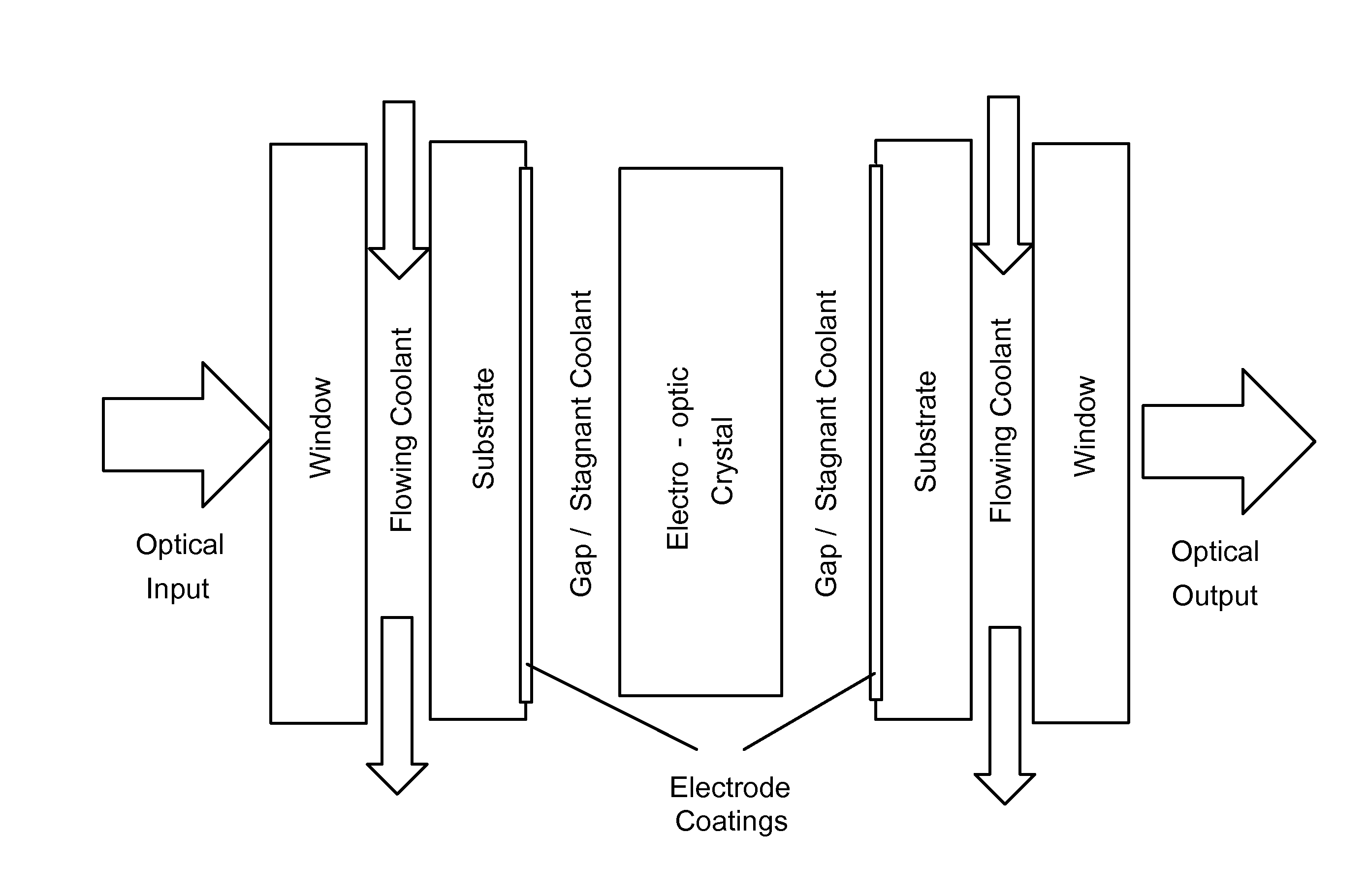
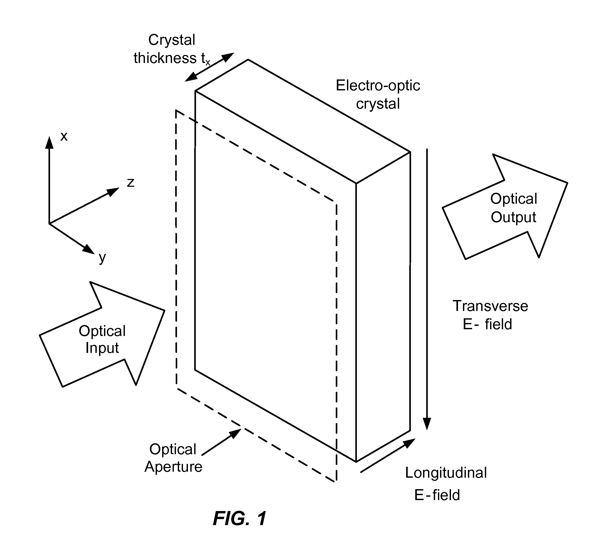
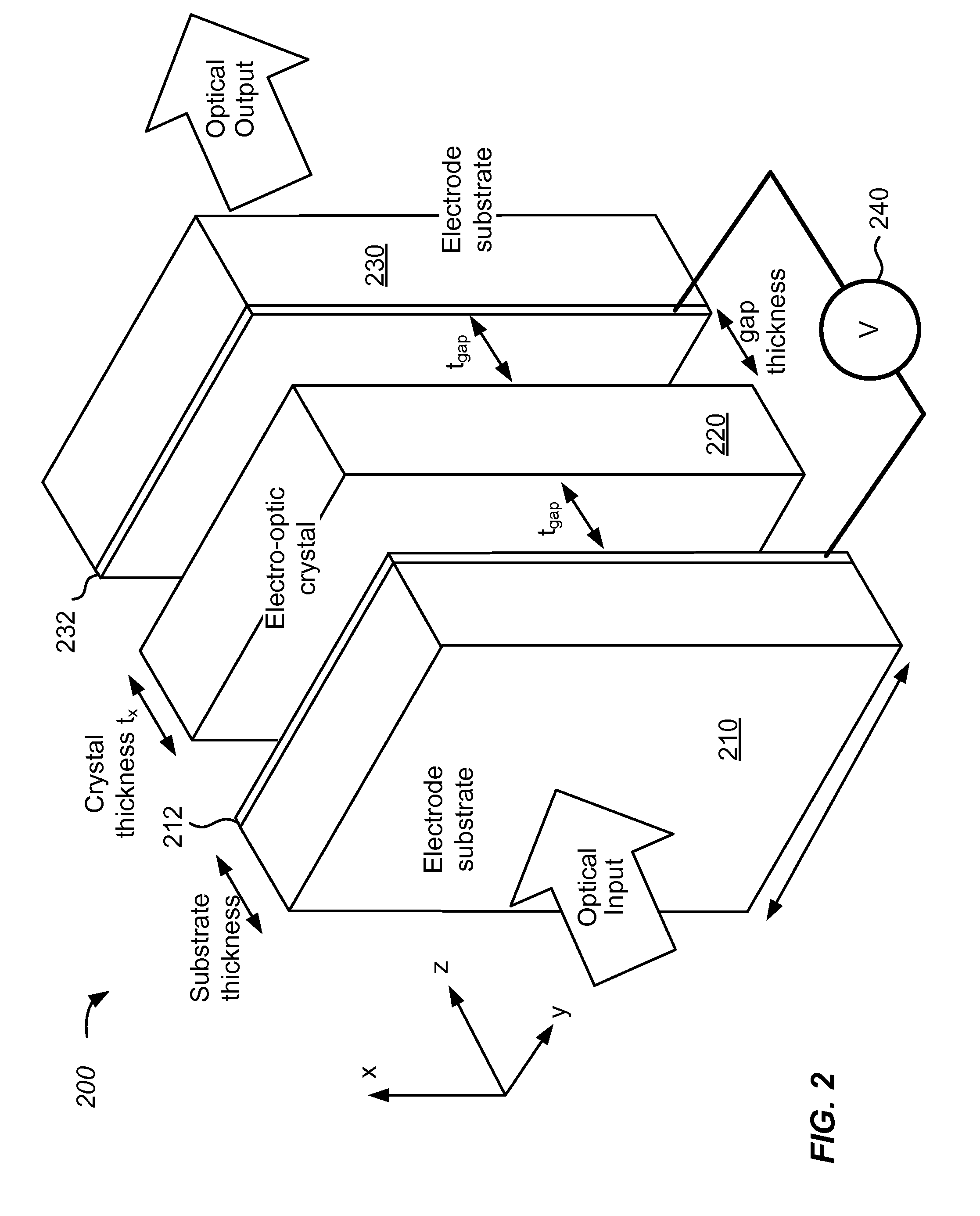
[0021]According to embodiments of the present invention, optical switches are provided in the form of Pockels cells with longitudinal electrode geometries. According to some embodiments of the present invention, the drive voltage is independent of crystal thickness and the crystal is isotropic in the aperture plane. As described below, the electrodes used to apply the electrode field overlap with the optical aperture, and therefore are transparent or semi-transparent to permit optical propagation.

[0022]Pockels cells with ring electrodes leave a portion of the crystal surface unexposed, but use a thicker crystal (i.e., a higher thickness: aperture ratio) in order to achieve a longitudinal electric field with reduced fringing effects. Accordingly, this design results in increased absorption and thermal birefringence. As a result, it is difficult to scale ring electrode devices to large aperture. Longitudinal devices with plasma (low pressure gas phase) electrodes have been constructed...


PUM

PropertyMeasurementUnit
sizeaaaaaaaaaa
switching voltageaaaaaaaaaa
thicknessesaaaaaaaaaa

Abstract

An electro-optic device includes an electro-optic crystal having a predetermined thickness, a first face and a second face. The electro-optic device also includes a first electrode substrate disposed opposing the first face. The first electrode substrate includes a first substrate material having a first thickness and a first electrode coating coupled to the first substrate material. The electro-optic device further includes a second electrode substrate disposed opposing the second face. The second electrode substrate includes a second substrate material having a second thickness and a second electrode coating coupled to the second substrate material. The electro-optic device additionally includes a voltage source electrically coupled to the first electrode coating and the second electrode coating.

Description

STATEMENT AS TO RIGHTS TO INVENTIONS MADE UNDER FEDERALLY SPONSORED RESEARCH OR DEVELOPMENT[0001]The United States Government has rights in this invention pursuant to Contract No. DE-AC52-07NA27344 between the United States Department of Energy and Lawrence Livermore National Security, LLC, for the operation of Lawrence Livermore National Security.BACKGROUND OF THE INVENTION[0002]Current optical switch technologies for high energy / high power laser beams use an electro-optical Pockels Cell based on deuterated potassium dihydrogen phosphate (DKDP) switch crystals, with electric fields applied either in a longitudinal or transverse orientation as shown in FIG. 1. The applied electric field changes the polarization of light beam, and the polarization changes can be converted to intensity modulation and redirection using external polarizers. Devices based on transverse electrode geometries have two drawbacks: they require a large switching voltage (>55 kV at a 25 cm aperture) that inc...

Claims


Application Information

Patent Timeline
Patent Type & Authority Applications(United States)
IPC IPC(8): G02F1/03G02F1/00G02F1/29
CPCG02F1/0305G02F1/0311G02F1/0322G02F1/0327G02F2201/38G02F2203/01G02F2203/02G02F2203/60G02F1/03
Inventor DERI, ROBERT J.RHODES, MARK A.BAYRAMIAN, ANDREW J.CAIRD, JOHN A.HENESIAN, MARK A.EBBERS, CHRISTOPHER A.
Owner LAWRENCE LIVERMORE NAT SECURITY LLC
Why Eureka
Try Eureka