Bistable molecular mechanical devices with a middle rotating segment activated by an electric field for electronic switching, gating, and memory applications

a molecular mechanical device and rotating segment technology, applied in the field of molecular systems, can solve the problems of slow switching time of molecules, irreversible switches, and large energy expenditure to toggle switches, and achieve the effect of fast switching time, easy and cheap production

Inactive Publication Date: 2004-04-08
SAMSUNG ELECTRONICS CO LTD
View PDF5 Cites 15 Cited by
  • Summary
  • Abstract
  • Description
  • Claims
  • Application Information

AI Technical Summary

Benefits of technology

[0010] The present invention introduces a new type of switching mechanism, namely, an electric field induced rotation of a rotatable middle section (rotor) of a molecule. Thus, the molecule is neither oxidized nor reduced in the toggling of the switch, which avoids the necessity of breaking chemical bonds and potentially initiating a nonreversible reaction. Also, the part of the molecule that moves is quite small, so the switching time should be very fast. Also, the molecules are much simpler and thus easier and cheaper to make than the rotaxanes and related compounds.

Problems solved by technology

The primary problem with the rotaxane was that it is an irreversible switch.
This requires the expenditure of a significant amount of energy to toggle the switch.
In addition, the large and complex nature of rotaxanes and related compounds potentially makes the switching times of the molecules slow.
The primary problems with the catenanes are small ON-to-OFF ratio and a slow switching time.

Method used


Image

  • Bistable molecular mechanical devices with a middle rotating segment activated by an electric field for electronic switching, gating, and memory applications
  • Bistable molecular mechanical devices with a middle rotating segment activated by an electric field for electronic switching, gating, and memory applications
  • Bistable molecular mechanical devices with a middle rotating segment activated by an electric field for electronic switching, gating, and memory applications

Examples


example 2b

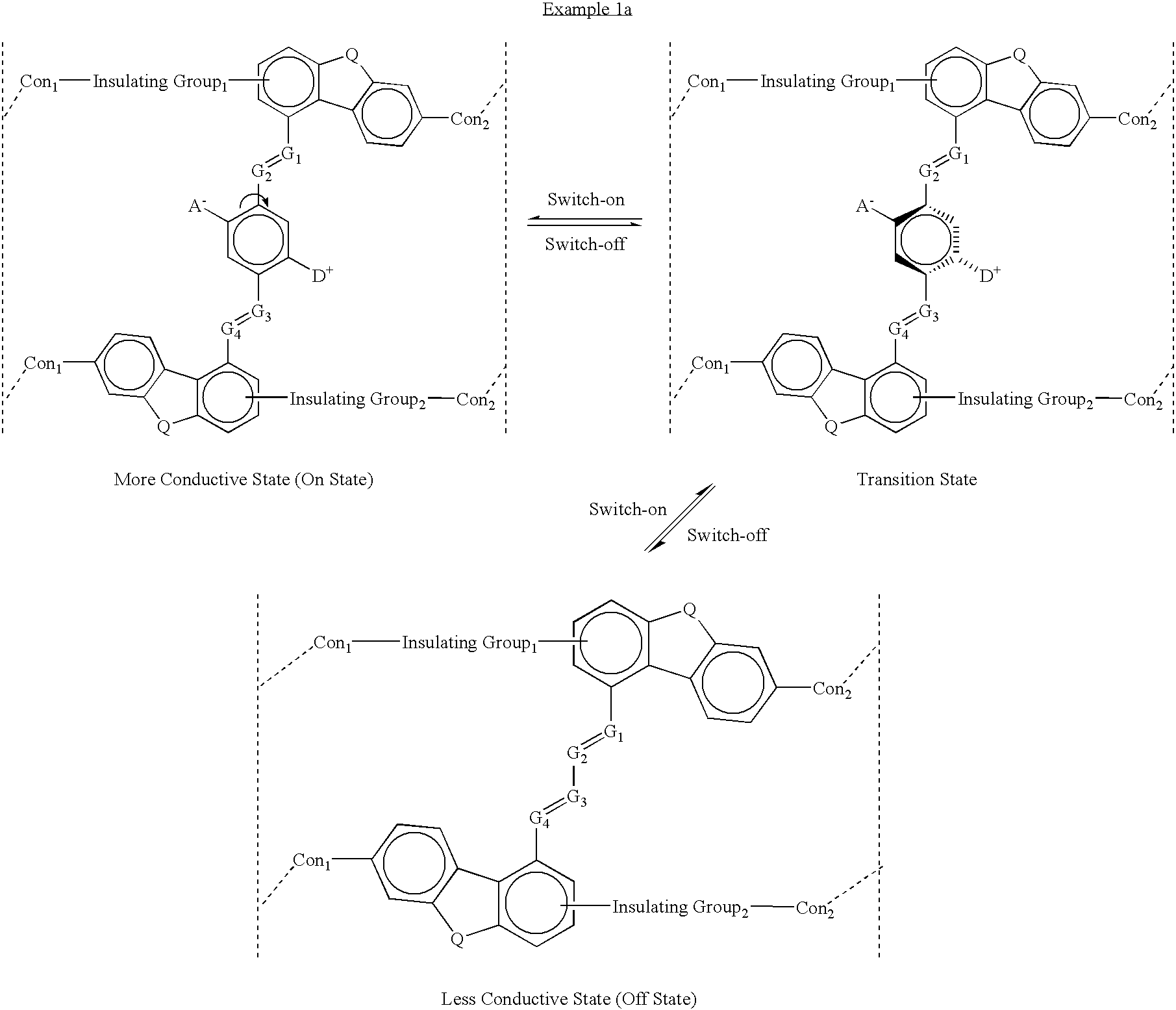
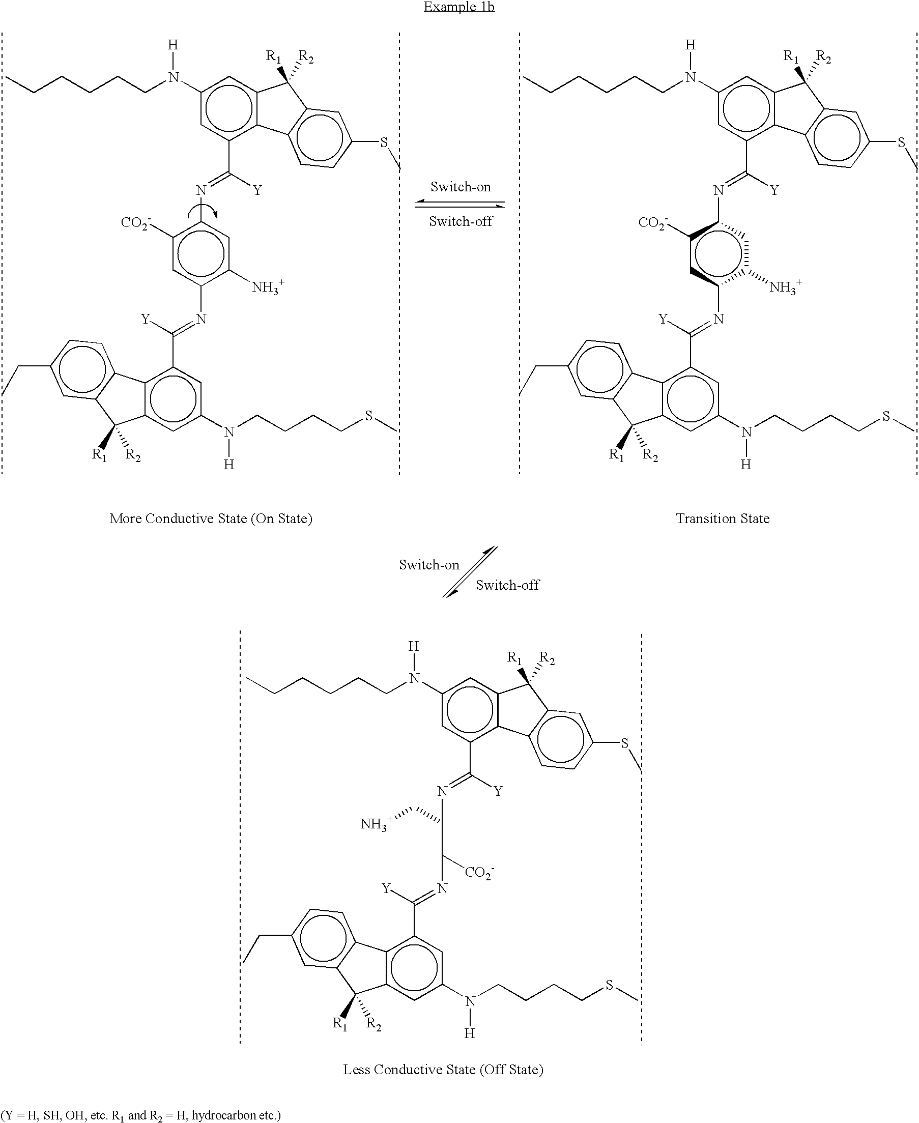
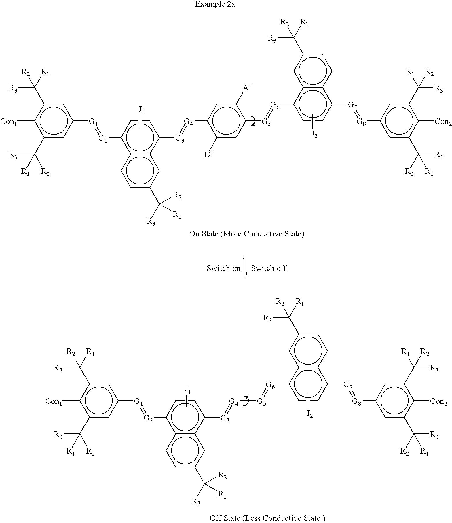
[0097] The molecule shown above (Example 2b) has been designed with the internal rotor parallel to the orientation axis of the entire molecule. In this case, the external field is applied perpendicular to the molecular axis--the electrodes are oriented parallel to the long axis of the molecule and can be either perpendicular or parallel to the plane of the above model structures. For example, application of an electric field to the upper molecule shown above where the field lines are perpendicular to the molecular axis and pointing upward will cause the rotor as pictured in that diagram to rotate to approximately 90 degrees and appear edge on, as shown in the lower molecular diagram above, and vice versa. In this case, the rotor as pictured in the lower diagram is not coplanar with the rest of the molecule, so this is the OFF or low conductivity state of the molecule, whereas the rotor is coplanar with the rest of the molecule on the upper diagram, so this is the ON or high conducti...


PUM

PropertyMeasurementUnit
angleaaaaaaaaaa
sizeaaaaaaaaaa
heightsaaaaaaaaaa

Abstract

A molecular system is provided for electric field activated switches, such as a crossed-wire device or a pair of electrodes to which the molecular system is linked by linking moieties. The crossed-wire device comprises a pair of crossed wires that form a junction where one wire crosses another at an angle other than zero degrees and at least one connector species connecting the pair of crossed wires in the junction. The connector species comprises the molecular system, which has an electric field induced band gap change, and thus a change in its electrical conductivity, that occurs via one a molecular conformation change, based on a rotor / stator construction of the molecular system, involving a rotating portion (rotor) connected between to stationary portions (stators). Nanometer-scale reversible electronic switches are thus provided that can be assembled easily to make cross-bar circuits, which provide memory, logic, and communication functions.

Description

[0001] The present application is a continuation-in-part application of Ser. No. 09 / 823,195, filed Mar. 29, 2601, which in turn is a continuation-in-part application of Ser. No. 09 / 759,438, filed Jan. 12, 2001, which in turn is a continuation-in-part application of Ser. No. 09 / 738,793, filed Dec. 14, 2000.[0002] The present application is also related to the following applications and patents: Ser. Nos. 09 / 280,048 ("Chemically Synthesized and Assembled Electronic Devices"); 09 / 280,225 ("Molecular Wire Crossbar Interconnects for Signal Routing and Communications"); 09 / 282,045 ("Molecular Wire Crossbar Logic"); 09 / 282,049 ("Demultiplexer for a Molecular Wire Crossbar Network"); and 09 / 280,188 ("Molecular Wire Transistors"), all filed on Mar. 29, 1999, and U.S. Pat. No. 6,128,214, issued on Oct. 3, 2000 ("Molecular Wire Crossbar Memory").[0003] The present application is an improvement over the foregoing applications and patent in that it is directed to a class of molecules that provid...

Claims


Application Information

Patent Timeline
Patent Type & Authority Applications(United States)
IPC IPC(8): C07C323/45B82B1/00G02B26/02G02F1/15G02F1/17G11C13/02G11C13/04G11C23/00H01L27/10H01L27/28H01L49/02H01L51/05H01L51/30H01M8/04
CPCB82Y10/00Y02E60/50G02F1/174G11C13/0014G11C13/02G11C13/04G11C23/00G11C2213/14G11C2213/77G11C2213/81H01L51/0058H01L51/0595H01M8/04007H01M8/04089H01M8/04097G02F1/15G11C13/041G02B26/026H10K19/202H10K85/626H10K10/50H10K10/701B82B1/00H10K10/00
Inventor ZHANG, XIAO-ANWILLIAMS, R. STANLEYWALMSLEY, ROBERT G.VINCENT, KENT
Owner SAMSUNG ELECTRONICS CO LTD
Why Eureka
Try Eureka