Power source for regulated operation of the deflection coil of an x-ray tube

a technology of x-ray tube and deflection coil, which is applied in the direction of x-ray tube, electrical apparatus, electric discharge tube, etc., can solve the problems of power amplifiers operating with too low efficiency, assembly requires a large structural volume, and inductive transformation in power supplies does not allow sufficiently fast modulation of current, etc., to achieve fast and exact generation of coil current and high efficiency

Active Publication Date: 2006-07-25
SIEMENS HEALTHCARE GMBH
View PDF3 Cites 19 Cited by
  • Summary
  • Abstract
  • Description
  • Claims
  • Application Information

AI Technical Summary

Benefits of technology

[0011]An object of the present invention is to provide a power source for operation of the deflection coils of an x-ray tube that ensures a fast and exact generation of the coil current given simultaneously high efficiency. It is a further object of the invention to provide a power source for operation of an x-ray tube that enables a largely interference-proof regulation of the coil current.

Problems solved by technology

The back-and-forth movement of the electron beam between two separate focal spots or different focal spot shapes also is effected by somewhat complex and rapidly ensuing variations of the current in the deflection coils.
However, the inductive transformation in power supplies does not allow sufficiently fast modulation of the current.
However, this assembly requires a large structural volume.
Moreover, power amplifiers operate with too low an efficiency for the applications described above, Furthermore, the current cannot be regulated with a sufficient stability given large inductive loads (as the deflection coils are) due to their self-induction.
This arrangement enables sufficiently fast switch times in order to ensure a sufficiently fast variation of the coil current, however, the quantity to be varied, the coil current, is not taken into account in the activation of the power switches.
Moreover, the circuit does not suitably react given the occurrence of a failure of the x-ray voltage as a result of tube arcings.

Method used


Image

  • Power source for regulated operation of the deflection coil of an x-ray tube
  • Power source for regulated operation of the deflection coil of an x-ray tube
  • Power source for regulated operation of the deflection coil of an x-ray tube

Examples


Embodiment Construction

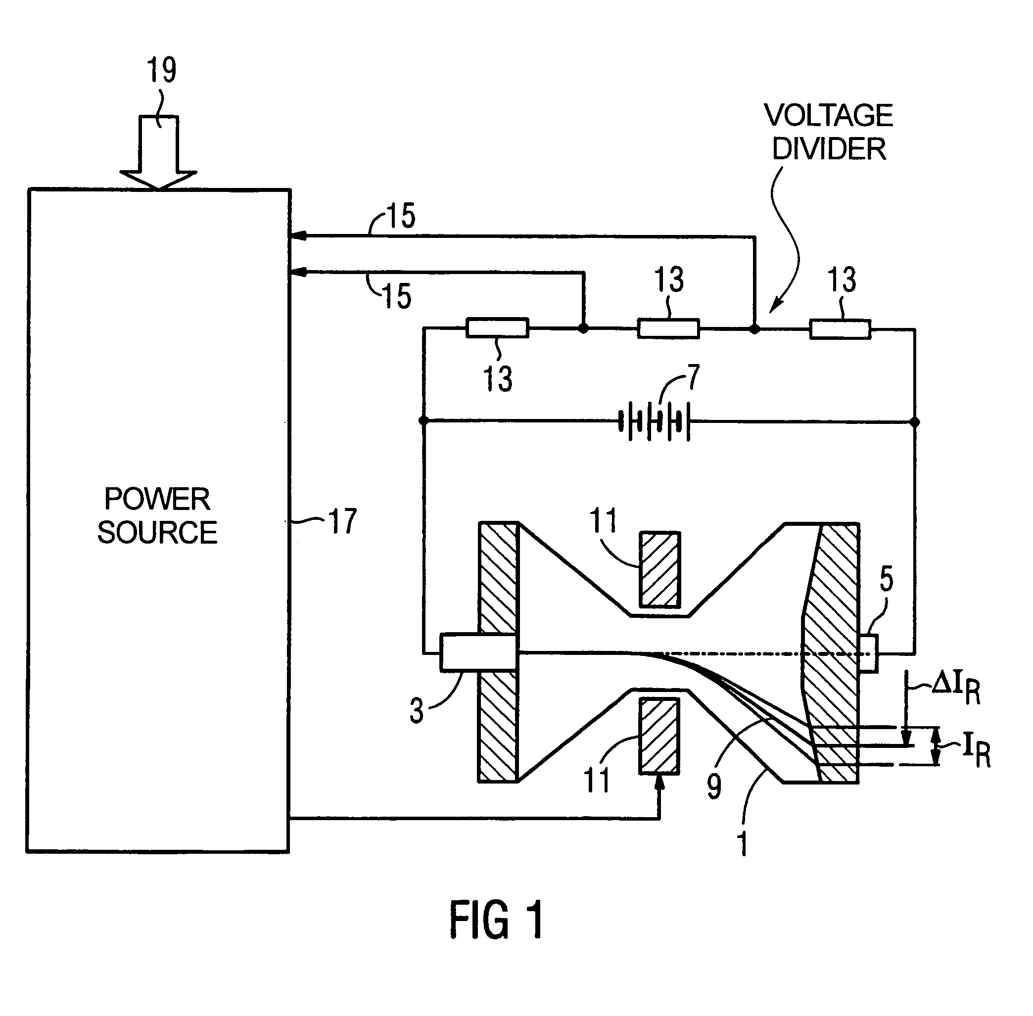
[0019]FIG. 1 shows an overview of a system composed of a power source 17, a deflection coil 11 and an x-ray tube 1. For simplification, the system is shown with only one deflection coil, (one deflection coil pair). To generate more complex focal spot contours and a larger number of focal spot positions, the system can be expanded to use a number of deflection coils 11, each charged with its own coil current.

[0020]Electrons are emitted from the cathode 3 of the x-ray tube 1 and are accelerated by the x-ray voltage to the anode 5. The x-ray voltage is generated by the x-ray voltage generator and directly influences the kinetic energy of the electrons, and thus indirectly the characteristic properties of the x-ray radiation generated by the x-ray tube 1. It Is varied depending on the application.

[0021]The electrons emitted by the cathode 3 form, within the x-ray tube 1, an electron beam 9 that is schematically shown in FIG. 1. The cathode 3 is designed such that the electron beam 9 is ...


PUM


Abstract

A power source for the operation of a deflection coil for an electron beam of an x-ray tube has a voltage source and a bridge circuit that is connected with each end of the deflection coil, respectively via one power switch in series connection to opposite poles of the voltage source. A current tap taps a coil current signal proportional to the current through the deflection coil. An activation comparator and a deactivation comparator are connected with the current tap to which an activation current signal Imin and a deactivation current signal Imax are supplied. The power switches are connected with the activation comparator and deactivation comparator such that they are closed in the event that the coil current signal undershoots the activation current signal Imin and opened in the event that the coil current signal overshoots the deactivation current signal Imax.

Description

BACKGROUND OF THE INVENTION[0001]1. Field of the Invention[0002]The present invention concerns a power source for operation of a deflection coil for an electron beam of an x-ray tube. The power source is of the type having a voltage source and a bridge circuit that is connected with each end of the deflection coil via, at each end, one power switch in series connection with opposite poles of the voltage source.[0003]2. Description of the Prior Art[0004]In x-ray devices, x-ray tubes are used to generate x-ray radiation. In the x-ray tube, electrons are accelerated by an electric field, at the x-ray voltage, from a cathode to an anode. Upon striking the anode, the electrons generate characteristic x-ray radiation as a result of their kinetic energy. The direction and form of the generated x-ray beam are determined by the condition and alignment of the surface of the anode as well as by the direction and focal spot contour of the electron beam striking on the anode. In order to generat...

Claims


Application Information

Patent Timeline
Patent Type & Authority Patents(United States)
IPC IPC(8): H05G1/52
CPCH05G1/52
Inventor DEURINGER, JOSEF
Owner SIEMENS HEALTHCARE GMBH
Why Eureka
Try Eureka