
Power supply system with self-heating function and vehicle

A power system, self-heating technology, applied in the field of power system, to achieve the effect of low cost and high efficiency

Active Publication Date: 2016-07-13
BEIJING INSTITUTE OF TECHNOLOGYGY
View PDF8 Cites 69 Cited by
  • Summary
  • Abstract
  • Description
  • Claims
  • Application Information

AI Technical Summary

Problems solved by technology

However, in the device described in the aforementioned Patent Document 1, in order to charge the secondary battery, regenerative braking during running or driving of the generator by the engine is always required.

Method used


Image

  • Power supply system with self-heating function and vehicle
  • Power supply system with self-heating function and vehicle
  • Power supply system with self-heating function and vehicle

Examples


Embodiment Construction

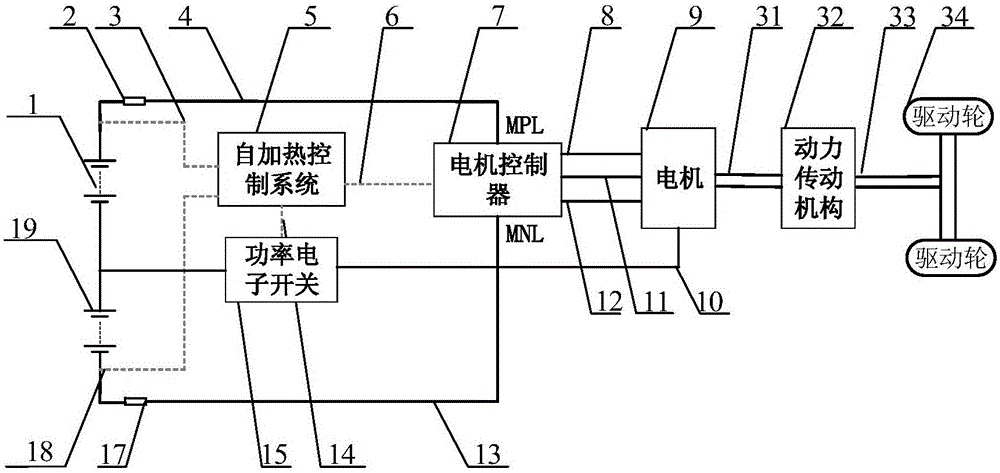
[0025] figure 1 It is a structural schematic diagram of the vehicle involved in the present invention. refer to figure 1 , the vehicle 100 includes power supply systems 1 and 19 and a driving force generating unit. The driving force generation unit includes a motor controller 7 , a motor 9 , a power transmission mechanism 32 between the motor and wheels 34 , and a drive shaft 33 .

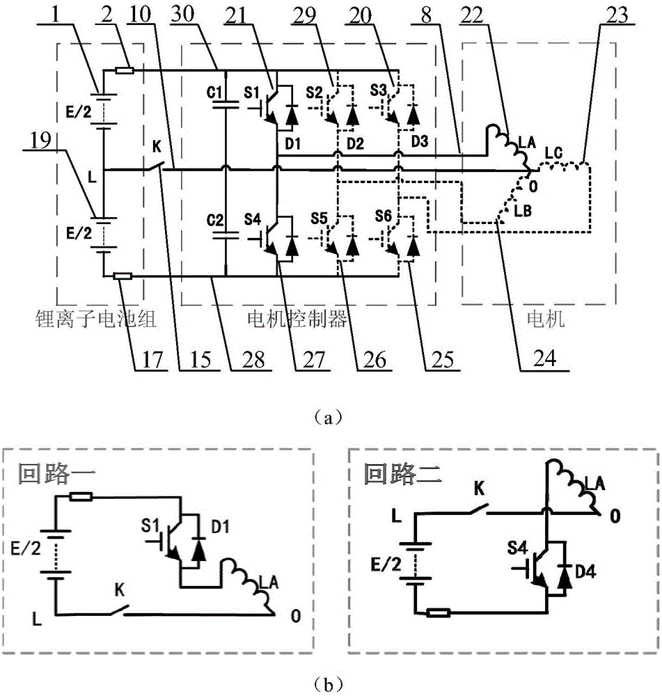
[0026] Motor controller 7 is connected in parallel to main positive bus MPL and main negative bus MNL. In addition, the motor controller 7 converts the drive power (DC power) supplied from the power supply systems 1 and 19 into AC power, and outputs it to the motor 9 . In addition, the motor controller 7 converts the AC power generated by the motor 9 into DC power, and outputs it to the power supply systems 1 and 19 as regenerative power. Such as figure 2 The shown motor controller 7 includes a control circuit (not shown) and an inverter circuit. The inverter circuit includes a bridge circuit...


PUM


Abstract

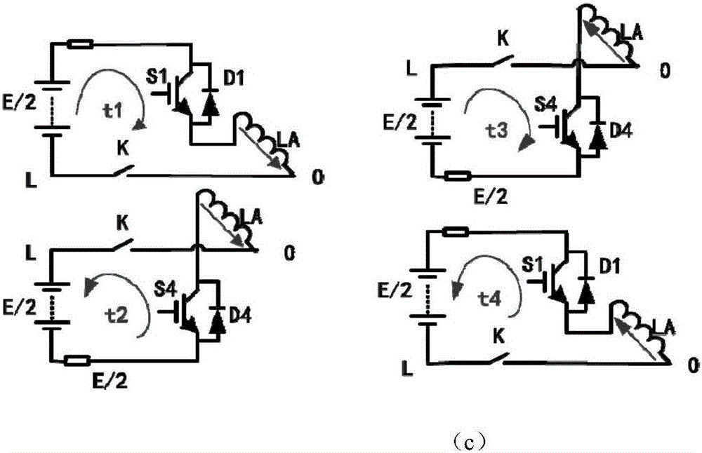
The invention relates to a power supply system with a self-heating function. An alternative-current self-heating loop consists of a first electrical storage device, a second electrical storage device, a power electronic switch, a motor controller and a motor, wherein a motor neutral point is electrically connected with an equipotential point between the first electrical storage device and the second electrical storage device through the power electronic switch; the power electronic switch is connected between the motor neutral point and the equipotential point in series. A power supply system device which is efficient and reliable, needs no external power supply device and has the self-heating function can be achieved, and moreover power supplied in the self-heating operation process is completely provided by a vehicle power supply system. The invention further relates to a vehicle.

Description

technical field [0001] The invention relates to a power supply system with a self-heating device, in particular to a power storage device based on alternating current with a self-heating device. Background technique [0002] Lithium-ion batteries are sensitive to low temperatures. The internal resistance of lithium-ion batteries rises sharply at low temperatures, and the discharge capacity and charge-discharge performance are greatly limited. This leads to insufficient power performance of electric vehicles in low-temperature environments, and the mileage of driving is greatly shortened. It is almost impossible to charge it when it is lower than 0°C. If it is charged forcibly, it is easy to cause an internal short circuit and cause a safety hazard. There are currently many solutions to the low-temperature use problem based on lithium-ion batteries. [0003] Currently, the main solution is to heat the battery pack. Among them, the patent CN102074769A proposes to use the cir...

Claims


Application Information

Patent Timeline
Patent Type & Authority Applications(China)
IPC IPC(8): H01M10/60H01M10/615B60L11/18
CPCH01M10/60H01M10/615B60L50/50Y02T10/70Y02E60/10H02M7/53871H02M1/32H02J7/0063H02P29/62H02P2209/01H02M3/1552H02M1/36B60L58/21B60L58/27B60L1/02B60L15/007
Inventor 孙逢春李军求张承宁董玉刚金鑫
Owner BEIJING INSTITUTE OF TECHNOLOGYGY
Learn More