
Pressure bulkhead structure with integrated selective electronic switch circuitry, pressure-isolating enclosure containing such selective electronic switch circuitry, and methods of making such

a technology of electronic switch circuitry and pressure isolating enclosure, which is applied in the direction of electrical equipment, borehole/well accessories, fluid removal, etc., can solve the problems of incomplete firing operation, inability to pre-test and/or verify the functionality and correct assembly of the entire gun string, and high cost and time delay

Active Publication Date: 2018-10-18
DYNAENERGETICS
View PDF2 Cites 70 Cited by
  • Summary
  • Abstract
  • Description
  • Claims
  • Application Information

AI Technical Summary

Benefits of technology

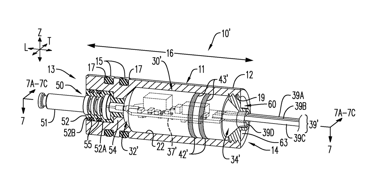
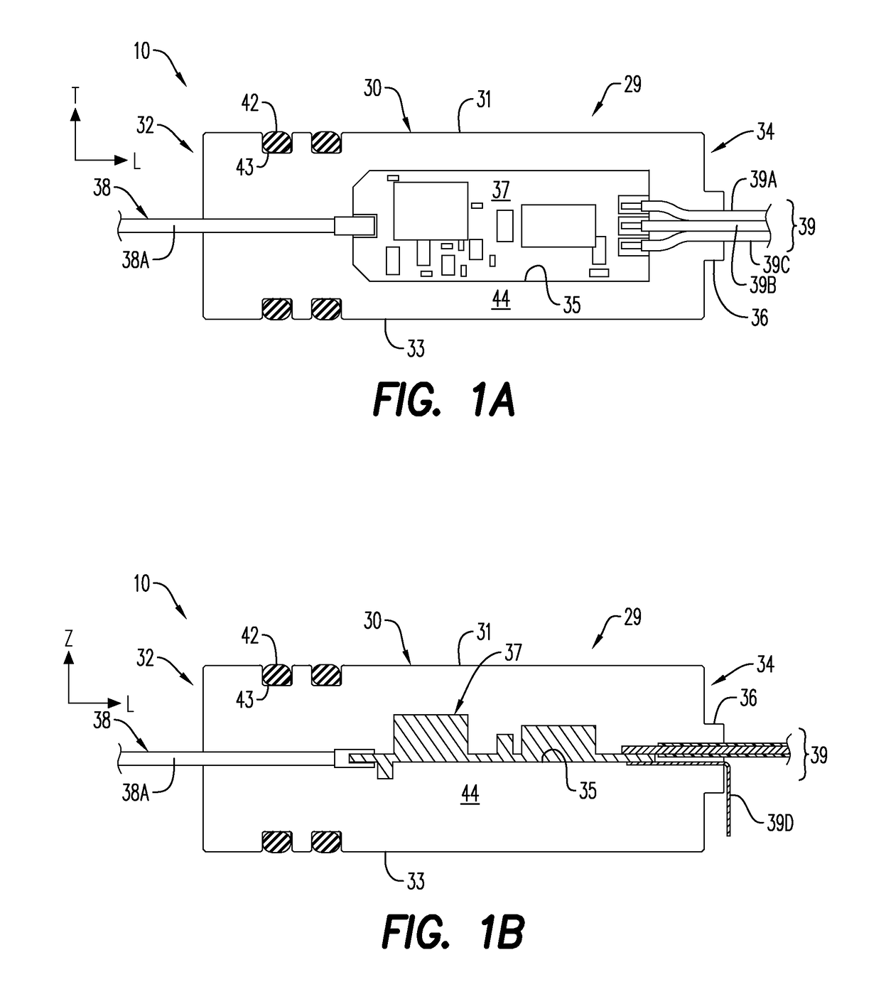
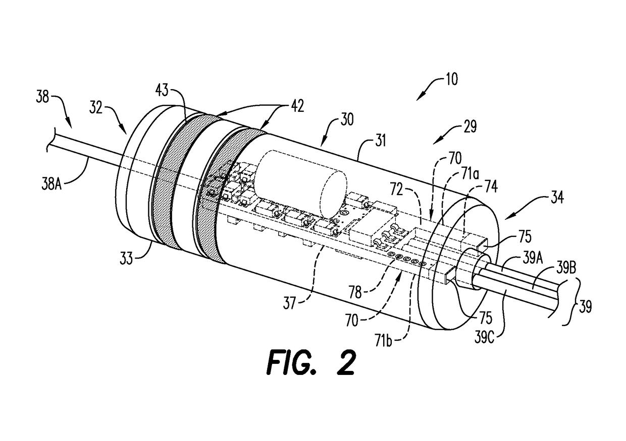
The patent describes a pressure bulkhead structure for a perforating gun select fire sub assembly. The structure includes an inner pressure-isolating enclosure with a selective electronic switch circuitry and an outer pressure-isolating enclosure with a conductive material. The selective electronic switch circuitry is positioned within the inner enclosure and makes electrical contact with a pin assembly outside the inner enclosure. The structure also includes a wiring arrangement and a common ground contact that make electrical contact with the conductive material of the outer enclosure. The technical effect of this structure is that it provides a pressure isolating barrier for the select fire sub assembly, protecting the components from environmental conditions and ensuring reliable operation.

Problems solved by technology

An interruption in the firing sequence of sequential gun modules (whether by failure of the simple electrical or mechanical switch) means that an entire firing operation would need to be aborted, adding much cost and time delay to a completion operation.
Further, the fact that only one gun module is electrically connected at any one time means that the entire gun string cannot be pre-tested and / or verified to be functional and correctly assembled.
Gun failure can only be found when it is too late in the completion operation and the gun operator may not be fully confident that the entire system will eventually work as desired.
While effective in providing detonation reliability and higher safety levels (i.e. avoiding inadvertent detonation from stray voltage fluctuations or intense RF frequencies which may be common around wellbore operations) such components may add material cost for the operators of such systems when compared to simpler diode type switch systems.
Such specific retainer devices, as those described in U.S. Pat. No. 9,291,040 to Hardesty et al., which is incorporated by reference in its entirety, require that distinct retainers (i.e. threaded pieces) be employed in a perforating gun assembly, thereby imparting potential equipment-specific limitations on operators of such systems.
Depending on particular design features, such retainer devices may also expose contained circuitry to environmental conditions of the surrounding wellbore (especially if they are not sufficiently electrically isolated or protected from the wellbore), thereby compromising the reliability or effectiveness of such switches during operation.
As a result, vibrations, shock-impact, or jarring movement associated with the conveying (pump-down operation) or retrieving of the equipment, or from detonation of gun modules in close proximity on a wireline, can cause components within the pressure bulkhead structures to shift about or contacts to be damaged, potentially leading to a misfire event or damage to the components that may be housed within such pressure bulkhead structures.
Such damage may occur even if the components have some fixed connection at one end of the pressure bulkhead.

Method used


Image

  • Pressure bulkhead structure with integrated selective electronic switch circuitry, pressure-isolating enclosure containing such selective electronic switch circuitry, and methods of making such
  • Pressure bulkhead structure with integrated selective electronic switch circuitry, pressure-isolating enclosure containing such selective electronic switch circuitry, and methods of making such
  • Pressure bulkhead structure with integrated selective electronic switch circuitry, pressure-isolating enclosure containing such selective electronic switch circuitry, and methods of making such

Examples


Embodiment Construction

[0037]Reference will now be made in detail to various embodiments. Each example is provided by way of explanation, and is not meant as a limitation and does not constitute a definition of all possible embodiments.

[0038]The terms “pressure bulkhead” and “pressure bulkhead structure” shall be used interchangeably, and shall refer to an internal, perforating gun housing compartment of a select fire sub assembly. In an embodiment, it also contains a pin assembly and allows the electrical passage of a wiring arrangement. The bulkhead structures may include at least one electrically conductive material within its overall structure.

[0039]The term “pressure-isolating” shall refer to the capacity of a structural component to withstand influence of at least pressure from all sides of a surrounding environment. The pressure-isolating capacity may be imparted by one or more of a variety of design techniques. For example, the shape and / or construction of the structural component itself (such as ...


PUM


Abstract

Pressure-isolating bulkhead structures with integrated selective electronic switches circuitry are provided. The pressure-isolating bulkhead structure may be a single unit having the integrated electronic switch circuitry, as well as an electrical connector that includes at least one of a wire and a pin contact. Such integrated selective electronic switch circuitry may be fashioned within a self-contained, inner pressure-isolating enclosure body. Such inner pressure-isolating enclosure body may be produced about the selective electronic switch circuitry such that the inner pressure-isolating enclosure body and switch circuitry are produced as a unit, which can be easily placed within a variety of bulkhead structures, and subsequently within a perforating gun.

Description

CROSS-REFERENCE TO RELATED APPLICATIONS[0001]This application claims priority to U.S. Provisional Application No. 62 / 553,483 filed Sep. 1, 2017, U.S. Provisional Application No. 62 / 515,178 filed Jun. 5, 2017, U.S. Provisional Application No. 62 / 505,365 filed May 12, 2017, and U.S. Provisional Application No. 62 / 486,903 filed Apr. 18, 2017, each of which is incorporated herein by reference in its entirety.FIELD[0002]The present disclosure relates generally to pressure bulkhead structures for use in perforating guns and perforating gun select fire sub assemblies / systems, the types of which are used for perforating wellbores of oil and natural gas wells. More specifically, the present disclosure relates to pressure isolating bulkhead structures for containing an electronic component, as well as individual structural components of such bulkheads.BACKGROUND[0003]Perforating guns are commonly used to convey and detonate explosive substances (shaped charges) within wellbores, with the ulti...

Claims


Application Information

Patent Timeline
Patent Type & Authority Applications(United States)
IPC IPC(8): F42D1/05E21B43/1185H05K5/06H05K5/00H05K5/02
CPCF42D1/05E21B43/1185H05K5/069H05K5/0056H05K5/0034H05K5/0065H05K5/0069H05K5/0247E21B43/117H05K5/065H05K5/064F42D1/045
Inventor EITSCHBERGER, CHRISTIANSCHARF, THILO
Owner DYNAENERGETICS
Learn More