Filter media support core

a technology of filter media and support core, which is applied in the direction of dispersed particle separation, separation process, transportation and packaging, etc., can solve the problems of difficult coalescing of radioactive hydrocarbons, and achieve the effects of enhancing the market appeal, long lasting, and little or no maintenan

Inactive Publication Date: 2017-04-04
PARKER HANNIFIN FILTRATION US INC
View PDF9 Cites 3 Cited by
  • Summary
  • Abstract
  • Description
  • Claims
  • Application Information

AI Technical Summary

Benefits of technology

[0026]The apparatus of the present invention is of a construction which is both durable and long lasting, and which will require little or no maintenance to be provided by the user throughout its operating lifetime. The apparatus of the present invention is also of inexpensive construction to enhance its market appeal and to thereby afford it the broadest possible market. Finally, all of the aforesaid advantages and objectives are achieved without incurring any substantial relative disadvantage. In another aspect, the invention provides.

Problems solved by technology

Currently, with many of the production sites, there are radical hydrocarbons that are a lot harder to coalesce such as in the fracking regions and certain oil and gas production regions.

Method used


Image

  • Filter media support core
  • Filter media support core
  • Filter media support core

Examples


Embodiment Construction

[0035]Referring to the FIGS. 1-7, FIG. 7 of the drawings designate an exemplary embodiment of a multi-stage vessel 100 for filter assembly 130. The multi-stage vessel 100 has a generally tubular hull 102 with one end permanently enclosed by a preferably elliptical cap 104 and the opposing end enclosed by a conventional closure member, preferably quick opening closure 106. It should be understood that a plurality of filter assemblies 130 can be removably installed in the multi-stage vessel 100.

[0036]Referring now to FIG. 7 in the drawings, the multi-stage vessel 100 is shown divided into the first stage portion 118 and the second stage portion 120 by a partition, or tubesheet 122. Tubesheet 122 forms a fluid-tight seal around the interior wall of the hull 102 and has a plurality of annular guides 124 through which a filter assembly 130 extends from the first stage portion 118 to the second stage portion 120. The tubesheet 122 and the guides 124 are preferably made of steel.

[0037]The ...


PUM

PropertyMeasurementUnit
lengthaaaaaaaaaa
diameteraaaaaaaaaa
diameteraaaaaaaaaa

Abstract

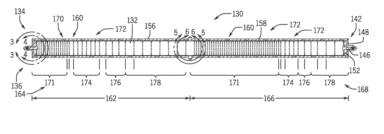
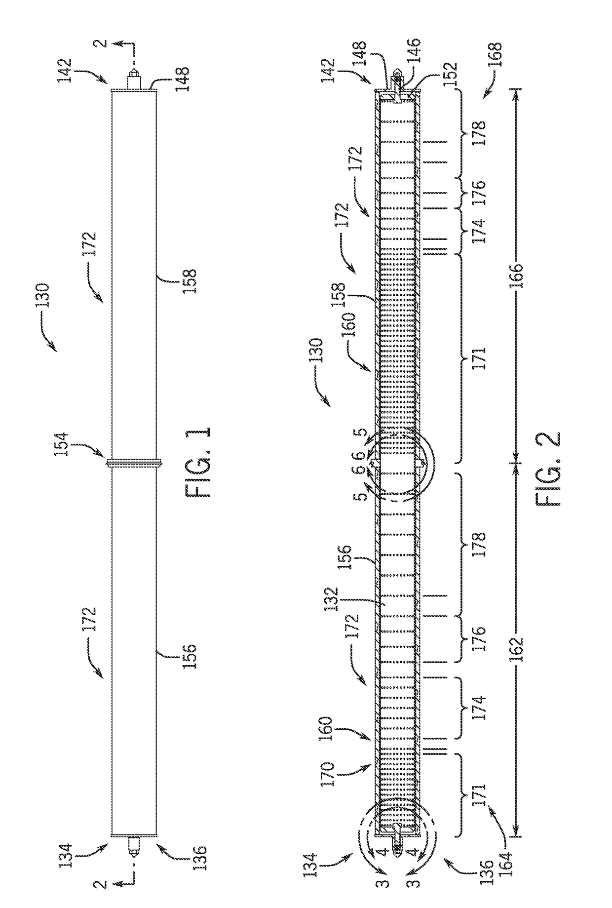
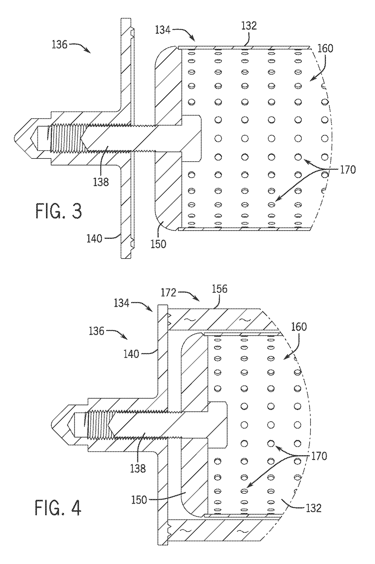
A single support core for a filter media assembly. The single support core includes a single longitudinal tube extending between a first end and a second end. A plurality of orifices are defined in the tube, the orifices align circumferentially along the longitudinal length of the tube. A first plurality of portions defined between the first end and an intermediate annular ring joint and a second plurality of portions defined between the intermediate annular ring joint and the second end. The orifices in each of the first portions and second portions are equidistance circumferentially from each other defining rings. The rings are equidistant longitudinally from each other in each of the portions and the rings are longitudinally spaced differentially in the adjacent portions. The plurality of orifices direct fluid flow through the tube to yield a high flow velocity in predetermined areas along the length of the filter assembly.

Description

CROSS-REFERENCE TO RELATED PATENT APPLICATIONS[0001]This patent application claims the benefit of U.S. Provisional Patent Application No. 62 / 058,237, filed Oct. 1, 2014, the entire teachings and disclosure of which are incorporated herein by reference thereto.FIELD OF THE INVENTION[0002]The present invention relates generally to separator / coalescer vessels and filter elements for such vessels, and more particularly to a filter media support member that is re-useable.BACKGROUND OF THE INVENTION[0003]Filter elements for separating solids and liquids from fluid streams, for example oil wells, are generally known in the prior art.[0004]Filtration vessels and coalescers are generally known in the prior art such as shown in U.S. Pat. No. 6,168,647 to Perry Jr. et al.; U.S. Publication Number 2012 / 0210688 to Burns et al.; U.S. Publication Number 2013 / 0062273 to Burns et al.; and U.S. Pat. No. 7,108,738 to Burns et al., the entire disclosures of each of these references being incorporated b...

Claims


Application Information

Patent Timeline
Patent Type & Authority Patents(United States)
IPC IPC(8): B01D46/00B01D46/24
CPCB01D46/0005B01D46/003B01D46/0024B01D46/2403B01D2265/06B01D46/64B01D46/0043
Inventor BURNS, DAVID JACK
Owner PARKER HANNIFIN FILTRATION US INC
Why Eureka
Try Eureka