[0008]Because the centrifugal clutch apparatus of the prior art noted above requires a press-formed vibration isolating ring having a complicated configuration, the manufacturing cost can be very high. In addition, there is the risk that a vibration isolating ring mounted on the outer circumferential surface of the driving plate would slip off from the driving plate due to the centrifugal force on the isolating ring. This risk of slippage requires a process for tightly and rigidly crimping the vibration isolating ring onto the driving plate so as to counter the centrifugal force. This method of crimping can also increase the manufacturing cost.
[0009]An aspect of at least one of the inventions disclosed herein includes the realization that centrifugal clutch apparatuses can be constructed more simply and with reduced cost while also suppressing generation of the “clutch squeal”, for example, by using a vibration reducing member in contact with an inner surface of a portion of the centrifugal clutch.
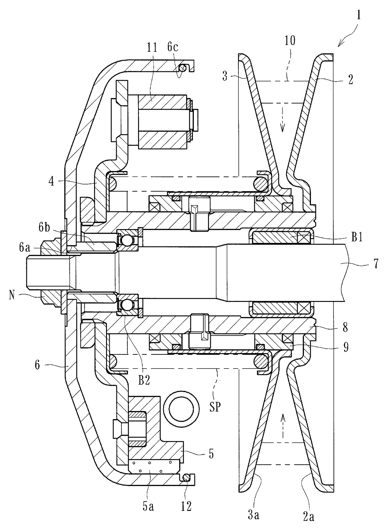
[0019]According to some embodiments, a centrifugal clutch apparatus can comprise a driving-side rotational member rotatable around a shaft member connected to a driving device. Clutch devices can be mounted on the driving-side rotational member and movable radially outward of the driving-side rotational member when a centrifugal force is exerted on the clutch devices. A driven-side rotational member can be rotatably independent from the driving-side rotational member and can be arranged for covering the driving-side rotational member, the driven-side rotational member, in some embodiments, having an inner circumferential surface configured to engage with the clutch devices moved radially outward. Friction members can be secured on surfaces of the clutch devices opposed to the inner circumferential surface of the driven-side rotational member. The friction members can be adapted to abut the inner circumferential surface of the driven-side rotational member so as to transmit the driving power of the driving device to the driven-side rotational member when the clutch devices are moved radially outward due to the centrifugal force. The inner circumferential surface of the driven-side rotational member can be formed with a groove. Furthermore, the centrifugal clutch apparatus further can include a tensioning member formed as a ring-shaped member able to be snap-fitted into the groove and held therein in a radially outward-biased condition. In such an embodiment, it can be possible to suppress generation of “clutch squeal” with a simple friction member structure and thus reduce manufacturing costs associated with reducing “clutch squeal.”
[0020]In some embodiments, the tensioning member is formed as an annular member having a cut-off portion in a part thereon and adapted to be snap-fitted into the groove by reducing its diameter at the cut-off portion, the tensioning member being held in the groove in a radially-outward biased condition exerted by its own spring-back elasticity. In such an embodiment, it can be possible to firmly mount the tensioning member within the groove and thus suppress generation of “clutch squeal.”
[0021]In some embodiments, the tensioning member is formed as an annular member having a cut-off portion in part thereon with one end of the cut-off portion being axially staggered from the other end of the cut-off portion. The tensioning member can be adapted to be snap-fitted into the groove by reducing its diameter. In some embodiments, the tensioning member is further configured to be held in the groove in a radially-outward biased condition and an axially-expanding biased condition exerted at the cut-off portion by its own spring-back elasticity. In such an embodiment, it is possible to firmly mount the tensioning member within the groove and thus suppress generation of “clutch squeal.”
[0022]In some embodiments, the tensioning member is formed as a substantially-annular member having a plurality of bent portions bent alternately in its axial direction and adapted to be snap-fitted into the groove by reducing the diameter of the tensioning member. The tensioning member can be configured to be held in the groove in a radially-outward biased condition exerted by its own spring-back elasticity and by the bent portions being contacted with walls of the groove. In such an embodiment, it is possible to urge and abut the tensioning member against the groove at multiple portions (e.g., at the axially projected portions at the bent portions of the tensioning member) and thus to efficiently suppress generation of “clutch squeal.”

