Shower apparatus

a technology for showering and showering utensils, which is applied to spraying utensils, spraying nozzles, liquid spraying utensils, etc., can solve the problems of unstable pulsation, impaired comfort of users of showering utensils, and flow rate of water flowing back through internal spaces from the direction of outer circumference toward the inner circumference, so as to increase the channel resistance of small spaces and stable pulsation

Active Publication Date: 2017-04-11
TOTO LTD
View PDF12 Cites 1 Cited by
  • Summary
  • Abstract
  • Description
  • Claims
  • Application Information

AI Technical Summary

Benefits of technology

[0015]In this way, the shower apparatus according to the present invention discharges bubbly water, and thus, it is possible for a user to enjoy a shower stream with a voluminous feel while the amount of water usage is reduced.
[0024]Intensive studies conducted by the present inventors have led to a new finding that, when all of the spaces have a uniform value for the above ratio, the flow rate of the backflow water that returns from the direction of the water discharge unit toward the throttle unit has a substantially uniform distribution, even if the small spaces have different shapes (even if the small spaces do not have a uniform channel resistance), so that the entire shower apparatus has a uniform period and phase of pulsation imparted to bubbly water (i.e., the backflow water has a uniform flow rate at any point in time among the streams of the backflow water). The present invention has been made based on such finding, and a simple technique of merely adjusting the above ratio allows bubbly water to be imparted with stable pulsation. It should be noted that the uniform ratio, among all of the small spaces, between a channel cross-sectional area at an inlet portion of each of the small spaces and a total opening area of the nozzle holes that communicate the small space with an external space encompasses not only ratios involving perfect matching but also ratios being set so as to be capable of providing stable pulsation.
[0026]In the preferred aspect of the invention described above, all of the small spaces have a uniform channel cross-sectional area at the inlet portion of the small space. With such configuration, backflow water that returns from the water discharge unit side (from the small spaces) toward the throttle unit has a more uniform flow-rate distribution, and this allows for stable pulsation to be provided. The uniform channel cross-sectional area, among all of the small spaces, at the inlet portion of the small space encompasses not only channel cross-sectional areas involving perfect matching but also cross-sectional areas being set so as to be capable of providing stable pulsation.
[0028]In the preferred aspect of the invention described above, all of the small spaces have a uniform channel width at the inlet portion of the small space when seen along a direction in which the bubbly water is discharged from the nozzle holes. Since the small spaces have a uniform channel cross-sectional shape at the inlet portion of the small space, backflow water that returns from the water discharge unit side (from the small spaces) toward the throttle unit has a more uniform flow-rate distribution, and this allows for stable pulsation to be provided. The uniform channel width, among all of the small spaces, at the inlet portion of the small space encompasses not only channel widths involving perfect matching but also channel widths being set so as to be capable of providing stable pulsation.
[0031]In the preferred aspect of the invention described above, in the vicinity of the inlet portion of at least one of the small spaces, a channel resistance increasing mechanism for increasing a channel resistance of the small space is arranged. For example, if channel resistance increasing mechanisms are arranged only in the vicinity of the inlet portions of the small spaces each having a linear internal channel (such small space having a relatively low channel resistance), the flow resistances of all the small spaces can be brought close to the same value. As a result, more stable pulsation can be provided.

Problems solved by technology

Meanwhile, such shower apparatus also reduces a stimulus sensation felt by a user when discharged bubbly water hits skin of the user, and this has been presented a problem in that a comfort feeling of the user of the shower apparatus is impaired.
However, when a part for discharging bubbly water (water discharge unit) has an external shape different from a circular shape (a rectangular shape, oval shape, etc.), the phase and period of pulsation provided to bubbly water differ depending on the position of a nozzle hole, and this may cause unstable pulsation.
Further, the flow rate of the water that flows back through an internal space from the direction of the outer circumference toward the inner circumference, which is backflow water that contributes to the generation of a swirl in the vicinity of a main water stream, is not uniform throughout the inside of the shower apparatus.
As a result, the size of a swirl that changes the direction of a main water stream, and the time when such swirl occurs, etc., will differ depending on the location, and the phase and period of pulsation provided to bubbly water are also not uniform in the entire shower apparatus (such phase and period will differ depending on the position of a nozzle hole).
Pulsations with different phases may temporarily offset each other, and this causes unstable pulsation as a whole.
That is, with such shape, the distance over which water ejected from the throttle unit reaches an outer circumferential end of the water discharge unit is not uniform in the entire shower apparatus, and such distance differs depending on the direction of ejection.
Therefore, it can be considered that the backflow water that returns toward the throttle unit does not have a uniform flow-rate distribution and, instead, that the flow rate of the backflow water is not uniform, depending on the return direction among the streams of the backflow water.
That is, although the flow rate of the backflow water varies over time, depending on the change in the traveling direction of the main water stream, it can be considered that, for example, the period of such variation will differ depending on the stream of the backflow water, leading to a non-uniform flow-rate distribution.
As a result, it can be considered that bubbly water is not imparted with uniform pulsation, resulting in unstable pulsation.
Thus, it is common for the small spaces to not have a uniform shape.
Such difference in channel shape does not lead to a uniform channel resistance among the small spaces and, instead, results in variations in channel resistances.

Method used


Image

  • Shower apparatus
  • Shower apparatus
  • Shower apparatus

Examples


Embodiment Construction

[0041]Embodiments of the present invention will now be described below with reference to the accompanying drawings. To facilitate understanding of the description, the same components in the respective drawings are denoted by the same reference numerals whenever possible and repetitive description thereof will be omitted.

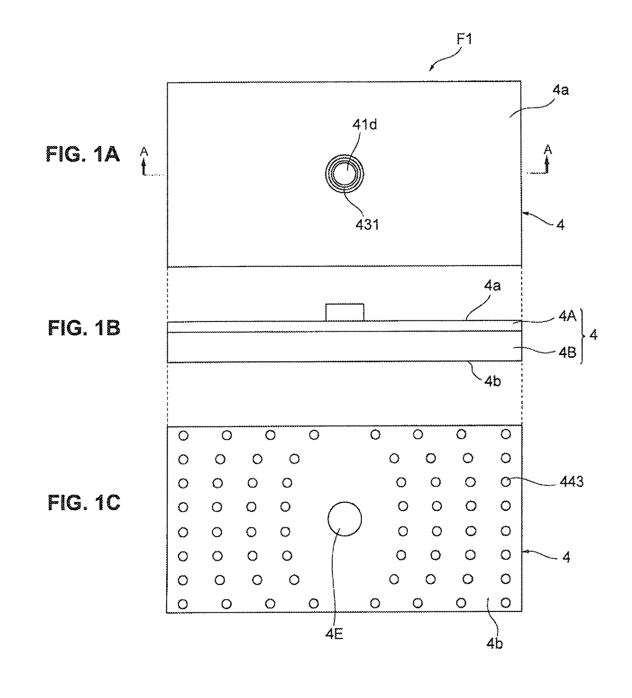
[0042]A shower apparatus, which is an embodiment of the present invention, will now be described with reference to FIGS. 1A, 1B and 1C, which are diagrams showing a shower apparatus F1 according to an embodiment of the present invention, in which FIG. 1A is a plan view, FIG. 1B is a side view, and FIG. 1C is a bottom view. As shown in FIG. 1A, the shower apparatus F1 is constituted by a body 4 which forms a rectangular shape in a top view, and a water supply port 41d is formed in a top face 4a of the shower apparatus F1 (body 4). The water supply port 41d is an inlet for water that is supplied from the outside.

[0043]As shown in FIG. 1B, the body 4 of the shower appa...


PUM


Abstract

In this shower apparatus, a part of an internal space thereof closer to the outer circumference thereof than an aeration unit is defined as a plurality of small spaces, and all of the small spaces have a uniform channel resistance, and all of the small spaces have a uniform ratio between a channel cross-sectional area at an inlet portion of each of the small spaces and a total opening area of nozzle holes that communicate the small space with an external space such that backflow water CF that returns from the respective small spaces consistently has a uniform flow rate at any point in time among the streams of the backflow water CF.

Description

BACKGROUND[0001]Field of the Invention[0002]The present invention relates to a shower apparatus that discharges aerated bubbly water.[0003]Description of Related Art[0004]A shower apparatus which discharges bubbly water by aerating water using a so-called ejector effect is known. Such shower apparatus can reduce the amount of water usage via aeration. Meanwhile, such shower apparatus also reduces a stimulus sensation felt by a user when discharged bubbly water hits skin of the user, and this has been presented a problem in that a comfort feeling of the user of the shower apparatus is impaired.[0005]In view of the above, the applicant has proposed the shower apparatus described in JP2012-187346 A. The shower apparatus described in JP2012-187346 A periodically varies the amount of air mixed into the water, whereby pulsation is provided to bubbly water to be discharged. Such pulsation is felt by the user of such shower apparatus as a stimulus sensation. As a result, a stimulus sensatio...

Claims


Application Information

Patent Timeline
Patent Type & Authority Patents(United States)
IPC IPC(8): B05B7/10B05B1/18B05B1/08B05B7/04
CPCB05B1/083B05B1/18B05B7/0425B05B1/08B05B7/0441B05B12/06
Inventor HAYATA, SHUHEITAKEDA, KOJIUEMURA, YASUFUMIUKIGAI, KIYOTAKENAGATA, KATSUYA
Owner TOTO LTD
Why Eureka
Try Eureka