Vehicle body structure

a technology for vehicle body panels and components, applied in the direction of superstructure connections, superstructure subunits, vehicle components, etc., can solve the problems of reducing the reducing the fatigue strength of aluminum alloy materials, and reducing the service life of the rear suspension tower, so as to achieve the effect of reducing the deformation of the first vehicle body panel, and improving the service li

Active Publication Date: 2017-04-11
TOYOTA JIDOSHA KK
View PDF13 Cites 14 Cited by
  • Summary
  • Abstract
  • Description
  • Claims
  • Application Information

AI Technical Summary

Benefits of technology

[0009]Preferred embodiments thus provide a vehicle body structure capable of improving the durability of a first vehicle body panel with respect to repeated input of forces when a vehicle is traveling, in a structure in which the first vehicle body panel that is made of die-cast aluminum is joined to a second vehicle body panel that is made of a metal material having a higher fatigue strength than the die-cast aluminum of the first vehicle body panel.

Problems solved by technology

However, when a wheel housing made of steel sheet and a rear suspension tower made of die-cast aluminum are directly joined together, durability may decrease (the life of the rear suspension tower may be shortened).
Aluminum alloy material has a lower fatigue strength than steel material, so if metal fatigue accumulates in the rear suspension tower due to this deformation repeatedly occurring in the rear suspension tower, it may lead to earlier failure.

Method used


Image

  • Vehicle body structure
  • Vehicle body structure
  • Vehicle body structure

Examples


first example embodiment

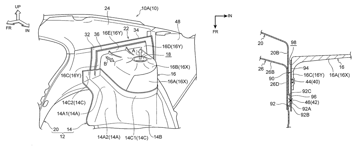
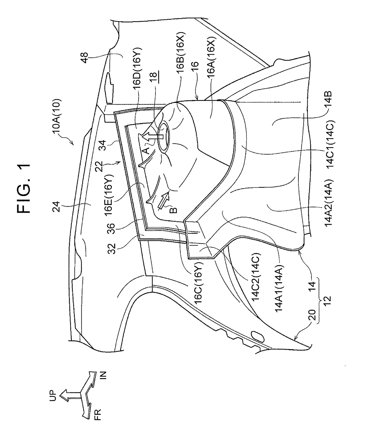
[0050]A vehicle rear structure according to a first example embodiment will now be described with reference to FIGS. 1 to 8B. In the drawings, arrow FR indicates a vehicle front side, arrow UP indicates a vehicle upper side, and arrow IN indicates a vehicle width direction inside.

[0051]

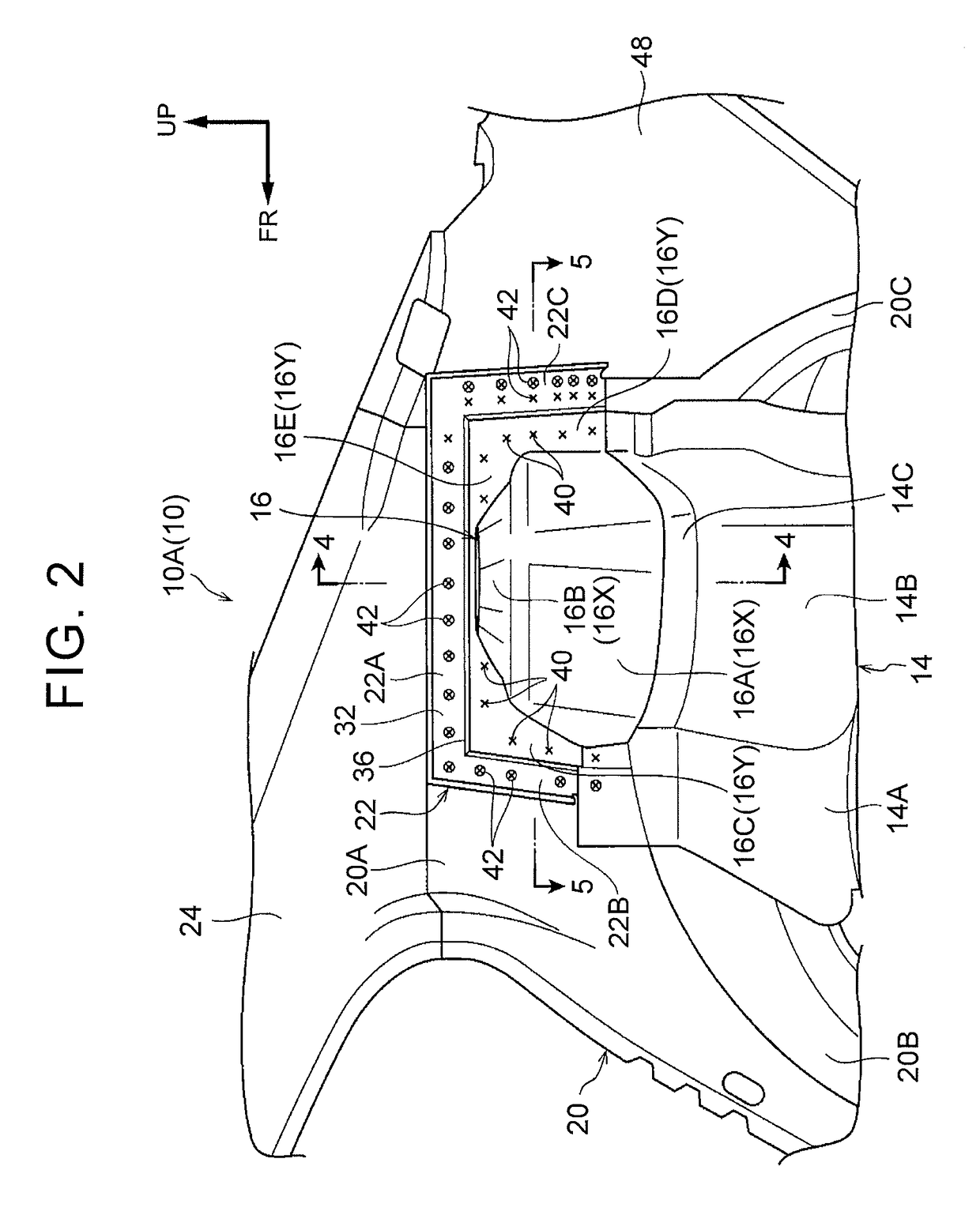
[0052]As shown in FIGS. 1 to 3, a wheel housing inner 14 that forms an inner panel of a rear wheel housing 12 and which has an upper end portion that is open and generally U-shaped, a rear suspension tower 16 that is joined fitted around the upper end portion of the wheel housing inner 14, a wheel housing outer 20 that is arranged on a vehicle width direction outside of the wheel housing inner 14 and forms an outer panel of the rear wheel housing 12, and an extension panel 22 that is interposed between the rear suspension tower 16 and the wheel housing outer 20, are all provided on a rear portion 10A of a vehicle 10. The rear suspension tower 16 is an example of a first vehicle body panel, the wheel h...

second example embodiment

[0091]Next, a vehicle rear portion according to a second example embodiment will be described with reference to FIG. 9. Component parts in the second example embodiment that are the same as those in the first example embodiment described above will be denoted by like reference characters, and descriptions thereof will be omitted.

[0092]As shown in FIG. 9, in this second example embodiment, a flat plate-shaped extension panel 90 without the step portion 36 described in the first example embodiment is used. Accordingly, an inner peripheral portion 94 and an outer peripheral portion 96 of the extension panel 90 are arranged on the same plane. Also, this extension panel 90 is also made of steel sheet. Further, the shape of the extension panel 90 in a side view is generally U-shaped similar to the extension panel 22 in the first example embodiment described above.

[0093]Meanwhile, a protruding portion 92 that protrudes toward the vehicle width direction inside is integrally formed on the w...


PUM


Abstract

In a vehicle rear structure that is one example of a vehicle body structure, a rear suspension tower that is made of die-cast aluminum and a wheel housing outer that is made of a metal material having a higher fatigue strength than the die-cast aluminum of the rear suspension tower, are joined together via an extension panel that is made of a metal material having a higher fatigue strength than the die-cast aluminum of the rear suspension tower. Further, a step portion is formed between an inner peripheral portion and an outer peripheral portion of the extension panel to form a deformable portion.

Description

INCORPORATION BY REFERENCE[0001]The disclosure of Japanese Patent Application No. 2014-265785 filed on Dec. 26, 2014 including the specification, drawings and abstract is incorporated herein by reference in its entirety.BACKGROUND[0002]1. Field of the Invention[0003]The disclosed embodiments relate to a vehicle body structure.[0004]2. Description of Related Art[0005]Japanese Patent Application Publication No. 2010-18087 (JP 2010-18087 A) describes a rear vehicle body portion of a vehicle. In summary, a vehicle body side wall of a vehicle body rear portion is formed by a side panel inner that forms a cabin inside wall surface, and a side panel outer that forms a vehicle body outside wall surface. Also, a lower portion of the side panel inner is a wheel arch portion that curves outward relative to a vehicle width direction. Moreover, in a vehicle side view, a reinforcement that extends in a vehicle up-down direction is arranged in the center portion of the wheel arch portion, and a cl...

Claims


Application Information

Patent Timeline
Patent Type & Authority Patents(United States)
IPC IPC(8): B62D29/00B62D27/02B62D25/08
CPCB62D25/088B62D27/023B62D29/00B62D29/008
Inventor SASAKI, TAKASHI
Owner TOYOTA JIDOSHA KK
Why Eureka
Try Eureka