Beam broadening with large spoil factors

a spoil factor and beam broadening technology, applied in the field of beam broadening with large spoil factor, can solve the problems of inability to accept, limited approach, and ripple in the main lobe, and achieve the effect of low power loss and fast sidelobe drop ra

a spoil factor and beam broadening technology, applied in the field of beam broadening with large spoil factor, can solve the problems of inability to accept, limited approach, and ripple in the main lobe, and achieve the effect of low power loss and fast sidelobe drop ra

US9620856B2Active Publication Date: 2017-04-11RAYTHEON CO

Image

  • Beam broadening with large spoil factors
  • Beam broadening with large spoil factors
  • Beam broadening with large spoil factors

Examples


Embodiment Construction

[0056]The detailed description set forth below in connection with the appended drawings is intended as a description of the presently preferred embodiments of methods of providing a broadened beam with large spoil factors, provided in accordance with the present invention, and is not intended to represent the only forms in which the present invention may be constructed or utilized. The description sets forth the features of the present invention in connection with the illustrated embodiments. It is to be understood, however, that the same or equivalent functions and structures may be accomplished by different embodiments that are also intended to be encompassed within the spirit and scope of the invention. As denoted elsewhere herein, like element numbers are intended to indicate like elements or features.

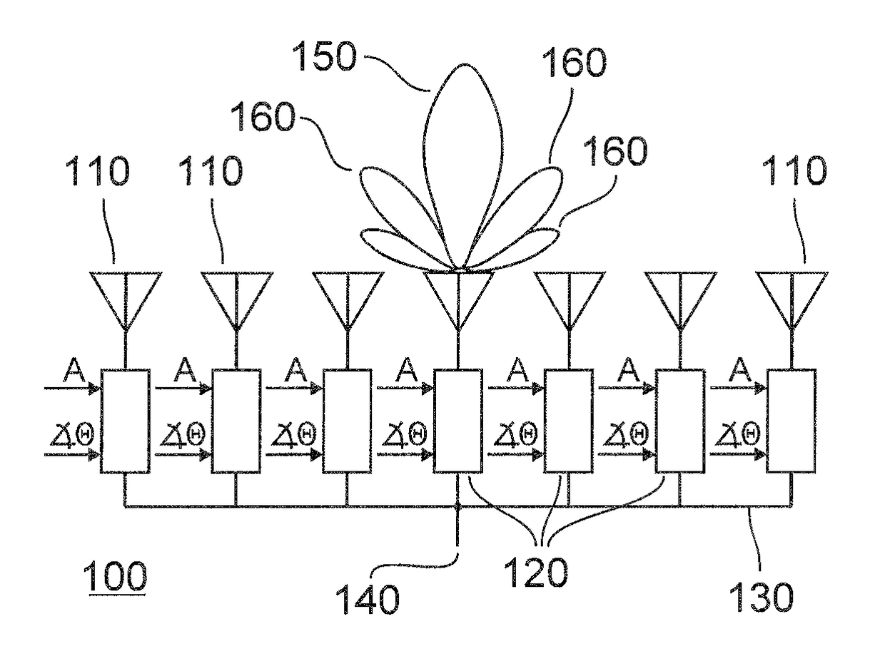
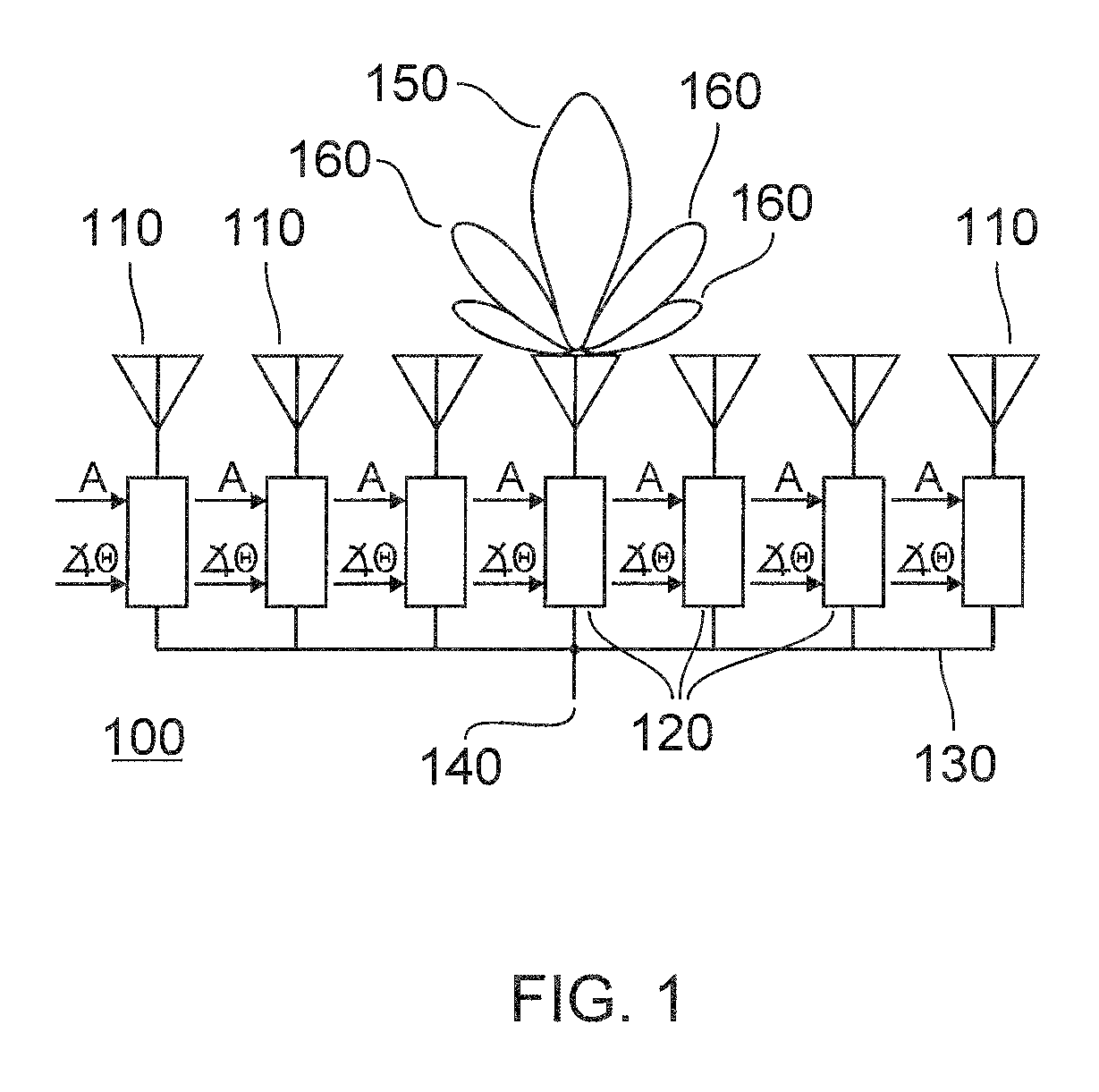
[0057]Referring to FIG. 1, an AESA antenna 100 includes several array elements 110, connected to transmit-receive modules 120. The transmit-receive modules 120 may be connected, th...


PUM


Abstract

Methods for generating weights for the antenna elements (110) in an AESA antenna (100). In one embodiment, transmitting weights are selected to have unit amplitude and quadratic phase, and receiving weights are selected to provide a two-way antenna pattern which is uniform over a useful portion (300) of the main lobe, and decreases rapidly outside of the uniform portion. In another embodiment the transmitting weights have unit amplitude over a central portion of the array and the receiving weights are selected to provide a two-way antenna pattern which is uniform over a useful portion (300) of the main lobe.

Description

BACKGROUND[0001]1. Field[0002]One or more aspects of embodiments according to the present invention relate to antenna beam shaping and more particularly to methods of providing a broadened beam with large spoil factors using an actively electronically scanned array antenna.[0003]2. Description of Related Art[0004]Large actively electronically scanned array (AESA) antennas are commonly used in intelligence, surveillance, and reconnaissance (ISR) radar systems, where such antennas provide improved resolution angle and the ability to transmit high power, and to distinguish slow-moving targets from stationary ones. Large antennas are also capable of forming narrower transmitting and receiving beams or, equivalently, an antenna pattern with a narrow main lobe.[0005]In synthetic aperture radar (SAR), if the signal processor has sufficient power, a wide antenna pattern is preferred, as it results in better mapping efficiency, i.e., an improved rate of mapping the ground. Moreover, it is de...

Claims


Application Information

Patent Timeline
11 Apr 2017
Publication
US9620856B2
IPC
G01S13/90; H01Q3/30; H01Q3/28; H01Q21/22; G01S13/02
CPC
H01Q3/30; G01S13/90; H01Q3/28; G01S2013/0254; H01Q21/22
Inventors
JIN, MICHAEL Y.