Battery connector and conductive terminal thereof

a technology of conductive terminals and battery connectors, which is applied in the direction of coupling contact members, coupling device connections, electrical apparatus, etc., can solve the problem that the compressive spring cannot be conveniently installed in the insulated housing, and achieve the effect of increasing the elastic force, effective compression, and improving structural reliability

Active Publication Date: 2017-04-11
ADVANCED CONNECTEK INC
View PDF7 Cites 5 Cited by
  • Summary
  • Abstract
  • Description
  • Claims
  • Application Information

AI Technical Summary

Benefits of technology

[0014]To sum up, the conductive terminal is of a spring type structure having a rectangular structure, thereby ensuring the conductive terminal can be telescoped in an electronic product and improving the structural reliability. In addition, multiple elastic arms are formed a spring type arm structure having forward and reverse V-shaped members sequentially wrapped, thereby forming multiple elastic arm members to increase the elastic force, which achieves effective compression and improves the elastic force of the conductive terminal, ensures the conductive terminal to contact the battery firmly even in strenuous vibration environment, and improves the product stability of the battery connector. Moreover, in the contacting portion, the contacting arm is extended and in contact with the elastic arm adjacent to the fixing portion. Electricity is transmitted in a shortest path from the contacting arm to the fixing portion, thereby shortening the path for electricity transmission and increasing a normal force for contacting the battery. Furthermore, the elastic connecting portions are sequentially arranged and disposed in the slots, thereby saving the assembly cost, reducing the product volume, and effectively improving the space utilization of the slots, which facilitate the product design of lightening and thinning and satisfy different use requirements.

Problems solved by technology

However, the members are not formed integrally, and during assembly, a long time and a machining process are required to install the compression spring between the metal pogo pin and the conductive base.
In addition, during installing the compression spring, the metal pogo pin and the conductive base would be bounced out by the compression spring so that the compressive spring cannot be installed in the insulated housing conveniently.

Method used


Image

  • Battery connector and conductive terminal thereof
  • Battery connector and conductive terminal thereof
  • Battery connector and conductive terminal thereof

Examples


Embodiment Construction

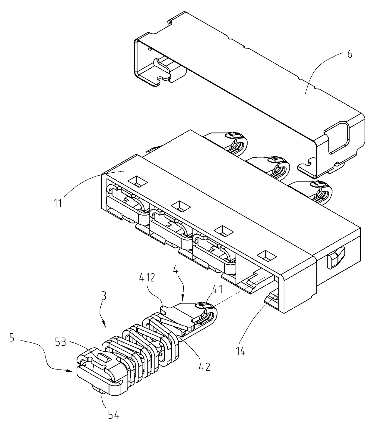
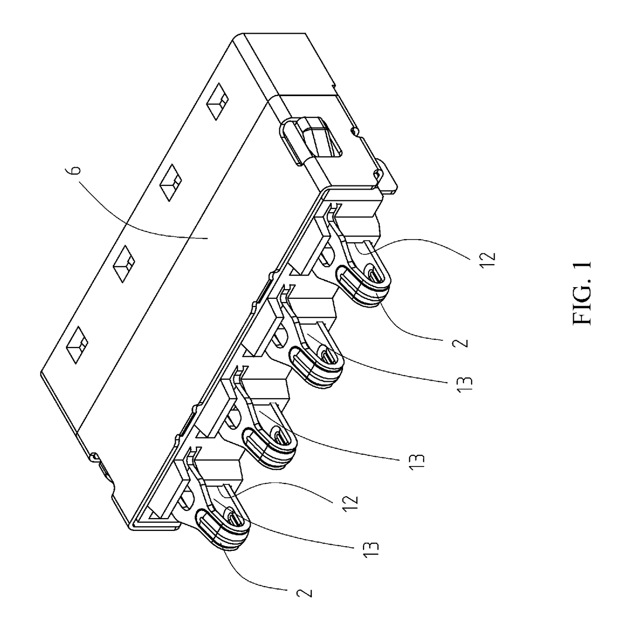
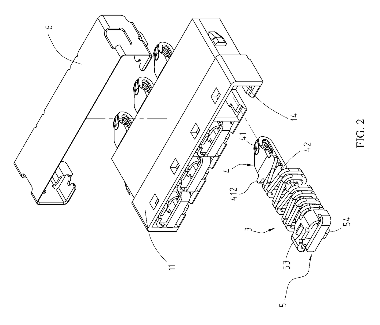
[0028]Referring to FIG. 1, FIG. 2, and FIG. 3, a first embodiment of the present disclosure is shown. FIG. 1 is a schematic exterior front view, FIG. 2 is a schematic exploded back view of FIG. 1, and FIG. 3 is a schematic exterior view of a conductive terminal. A battery connector 100 of the present disclosure is applicable to battery connection of products such as smart phones. The battery connector 100 comprises an insulated housing 11 and a plurality of conductive terminals 2, where a shell 6 covers the insulated housing 11, fixing sheets are extended from two sides of the shell 6 and can be soldered on a circuit board for fixing the battery connector 100 to the circuit board (not shown).

[0029]Referring to FIG. 1, FIG. 2, and FIG. 4, the insulated housing 11 is a rectangular base and includes a plurality of slots 12, a plurality of front openings 13, and a plurality of back openings 14. The slots 12 are sequentially arranged from left to right on the insulated housing 11 and sep...


PUM


Abstract

A battery connector includes an insulated housing and conductive terminals. The insulated housing includes slots. The conductive terminals are disposed in the slots, respectively. Each conductive terminal includes an elastic connecting portion, a contacting portion, and a fixing portion. The elastic connecting portion includes elastic arms and connecting portions. Each elastic arm is obliquely extending leftwards and rightwards, separated from each other, and arranged sequentially. The connecting portions are formed at two sides of the elastic arms, where each elastic arm forms a rectangular structure by being enclosed from one end to the other end. The contacting portion extends beyond one side of the corresponding slot. The contacting portion includes a bent contacting portion extending from a front side of the elastic connecting portion and bent backwards. The fixing portion extends from a back side of the elastic connecting portion and extends beyond the other side of the corresponding slot.

Description

CROSS-REFERENCES TO RELATED APPLICATIONS[0001]This non-provisional application claims priority under 35 U.S.C. §119(a) on Patent Application No. 201510055150.7 filed in China, P.R.C. on Feb. 3, 2015, the entire contents of which are hereby incorporated by reference.FIELD OF THE INVENTION[0002]The present disclosure relates to an electric connector, and in particular, to a battery connector and a conductive terminal thereof.BACKGROUND[0003]A conductive terminal of a common battery connector is designed to be a pogo pin conductive terminal. The pogo pin conductive terminal includes a metal pogo pin, a conductive base, and a compression spring installed inside an insulated housing. The metal pogo pin has a contacting end capable of protruding out of the insulated housing, the conductive base has a junction portion capable of being connected to a circuit board, and the compression spring is disposed between two side walls of the conductive base and has an upper end abutting against an i...

Claims


Application Information

Patent Timeline
Patent Type & Authority Patents(United States)
IPC IPC(8): H01R13/24
CPCH01R13/2428H01R13/24
Inventor CHEN, CHING-TIENDUAN, SHU-LINWAN, WEICHU, PING-CHUNGQI, XIAO-JUAN
Owner ADVANCED CONNECTEK INC
Why Eureka
Try Eureka