Paper feeding unit and image forming apparatus having the same

a feeding unit and image forming technology, applied in the field of paper feeding apparatus, can solve the problems of increased maintenance costs, increased manufacturing costs and noise, increased power consumption, etc., and achieve the effect of reducing material cost and installation spa

Active Publication Date: 2017-04-18
HEWLETT PACKARD DEV CO LP
View PDF9 Cites 0 Cited by
  • Summary
  • Abstract
  • Description
  • Claims
  • Application Information

AI Technical Summary

Benefits of technology

[0014]The present disclosure has been developed in order to overcome the above drawbacks and other problems associated with the conventional arrangement. An aspect of the present disclosure relates to a paper feeding apparatus that can selectively supply a print medium from two paper feeding trays using a single motor and can minimize material cost and installation space, and an image forming apparatus having the same.

Problems solved by technology

Accordingly, there are problems that arise such as an increase in material cost resulting in increased manufacturing cost and increased noise.
Also, power consumption is increased due to the rotation of the unnecessary feed roller, and the life of parts associated with the rotation of the feed roller, such as a feed roller, a shaft, a bush, etc., is reduced resulting in increased maintenance costs.
Accordingly, the power consumption is large because of the operation of the electronic clutch, and there is a risk of malfunction of the electronic clutch.
Also, since the electronic clutch and additional space for installation of the electronic clutch are needed, there is a problem that the material cost is increased.
However, for such a structure, since the additional motor and a space for installation of the additional motor are needed due to usage of the two motors compared to the case in which a single motor is used, there is a problem that the material cost is increased.

Method used


Image

  • Paper feeding unit and image forming apparatus having the same
  • Paper feeding unit and image forming apparatus having the same
  • Paper feeding unit and image forming apparatus having the same

Examples


first embodiment

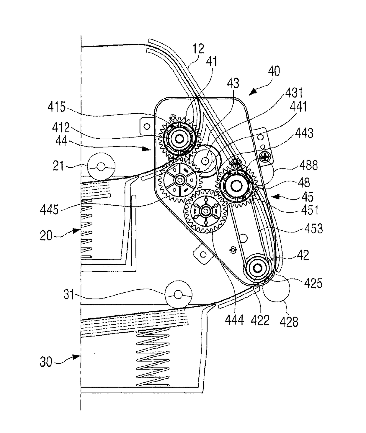
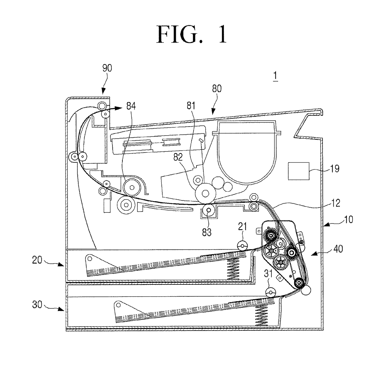
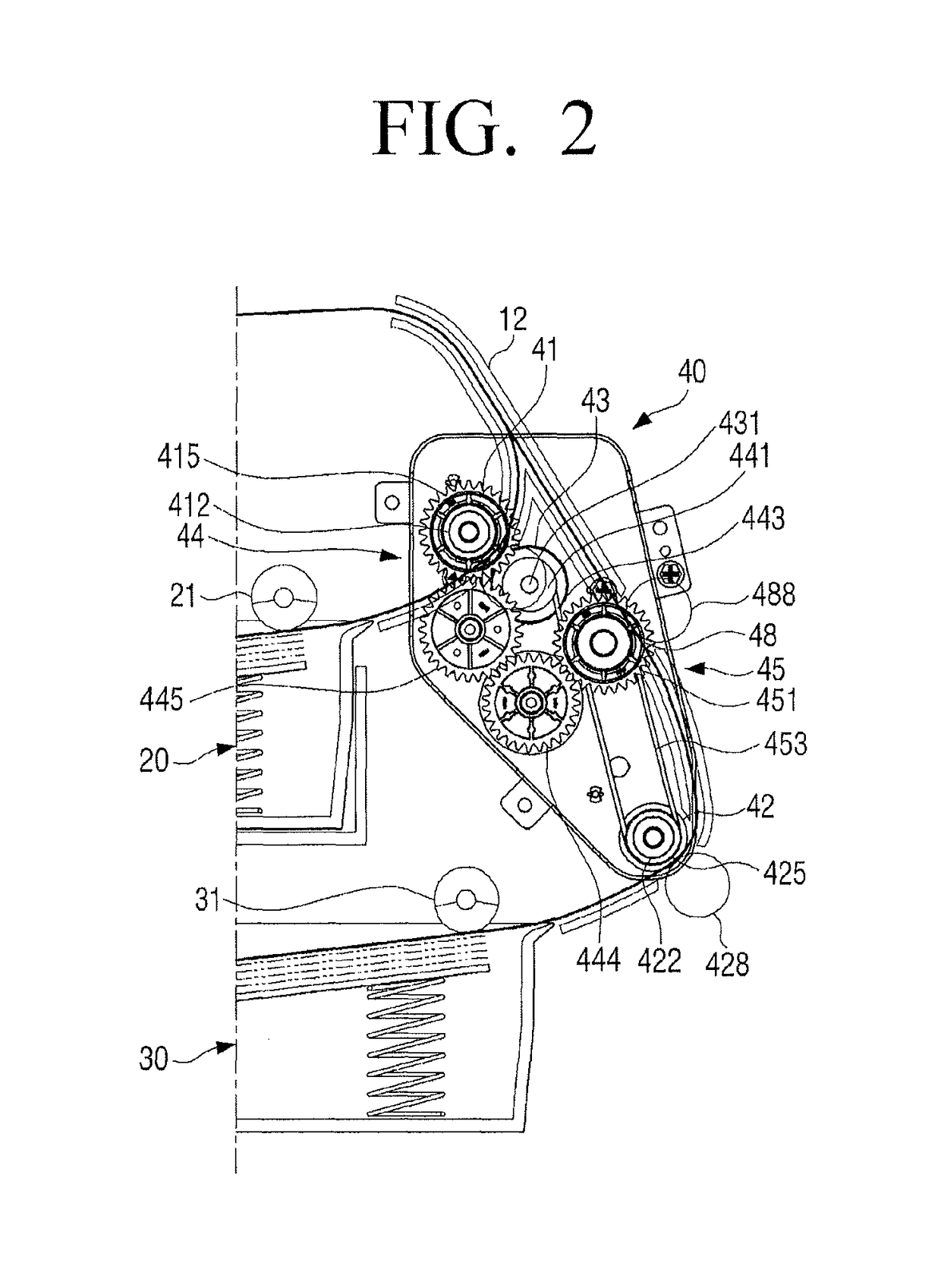
[0064]FIG. 1 is a cross-sectional view schematically illustrating an image forming apparatus including a paper feeding apparatus according to the present disclosure. FIG. 2 is a partial cross-sectional view illustrating the paper feeding apparatus of FIG. 1, and FIG. 3 is a perspective view illustrating the paper feeding apparatus of FIG. 1. FIG. 4A is a partial cross-sectional view illustrating when a first paper feeding tray of the paper feeding apparatus of FIG. 1 supplies a print medium, and FIG. 4B is a partial cross-sectional view illustrating when a second paper feeding tray of the paper feeding apparatus of FIG. 1 supplies a print medium.

[0065]Referring to FIG. 1, an image forming apparatus 1 according to an embodiment of the present disclosure may include, for example, a main body 10, two paper feeding trays 20 and 30, an image forming unit 80, a paper discharging unit 90, and a paper feeding apparatus 40.

[0066]The main body 10 forms an appearance of the image forming appar...

second embodiment

[0107]In a paper feeding apparatus 2 according to the present disclosure, the first and second paper feeding rollers are applied to first and second pickup rollers 210 and 220. As illustrated in FIG. 7, the paper feeding apparatus 2 according to an embodiment of the present disclosure may include, for example, first and second paper feeding trays 20 and 30, a drive source 240, first and second power transmission members 250 and 260, and first and second pickup rollers 210 and 220.

[0108]The drive source 240 may use the same as the drive source 43 of the paper feeding apparatus 40 according to the first embodiment of the present disclosure as described above. Therefore, a detailed description thereof is omitted. In the present embodiment, a motor capable of bi-directional rotation may be used as the drive source 240.

[0109]The first power transmission member 250 transmits the power of the motor 240 to the first pickup roller 210, and is configured of two gears in the present embodiment...

third embodiment

[0113]Hereinafter, a paper feeding apparatus for an image forming apparatus according to the present disclosure will be described with reference to FIGS. 8, 9A, and 9B.

[0114]FIG. 8 is a cross-sectional view schematically illustrating an image forming apparatus including a paper feeding apparatus according to a third embodiment of the present disclosure. FIG. 9A is a partial cross-sectional view illustrating when a first paper feeding tray of the paper feeding apparatus of FIG. 8 supplies a print medium, and FIG. 9B is a partial cross-sectional view illustrating when a second paper feeding tray of the paper feeding apparatus of FIG. 9 supplies a print medium.

[0115]Referring to FIG. 8, an image forming apparatus 3 according to an embodiment of the present disclosure may include, for example, a main body 10, two paper feeding trays 20 and 300, an image forming unit 80, a paper discharging unit 90, and a paper feeding apparatus 310.

[0116]The main body 10, the image forming unit 80, and ...


PUM


Abstract

A paper feeding apparatus for an image forming apparatus is provided. The paper feeding apparatus includes a first paper feeding roller, a first one-way rotation transmission member disposed coaxially on the first paper feeding roller to transmit a first one-way rotational force to the first paper feeding roller, a second paper feeding roller spaced apart from the first paper feeding tray, a second one-way rotation transmission member disposed coaxially on the second paper feeding roller to transmit a second one-way rotational force to the second paper feeding roller, a drive source to rotate the first and second paper feeding rollers, a first power transmission member disposed between the first one-way rotation transmission member and the drive source, and a second power transmission member disposed between the second one-way rotation transmission member and the drive source.

Description

CROSS-REFERENCE TO RELATED APPLICATIONS[0001]This application claims priority from Korean Patent Application No. 10-2014-0064248 filed May 28, 2014 in the Korean Intellectual Property Office, the disclosure of which is incorporated herein by reference in its entirety.BACKGROUND[0002]1. Field[0003]The present disclosure relates to a paper feeding apparatus. More particularly, the present disclosure relates to a paper feeding apparatus that can selectively supply a print medium from two paper feeding trays using a single motor and an image forming apparatus having the same.[0004]2. Description of the Related Art[0005]Image forming apparatuses including two or more paper feeding trays have been widely used.[0006]In general, a conventional image forming apparatus including two paper feeding trays includes two pickup rollers and two feed rollers in order to pick up and convey print media loaded in each of the two paper feeding trays. Accordingly, the conventional image forming apparatus ...

Claims


Application Information

Patent Timeline
Patent Type & Authority Patents(United States)
IPC IPC(8): B65H5/26B65H5/06
CPCB65H5/062B65H5/26B65H2403/40B65H2403/72B65H2403/722B65H2404/16B65H2405/332
Inventor LEE, CHANG-WOOJUNG, TAE-IL
Owner HEWLETT PACKARD DEV CO LP
Why Eureka
Try Eureka