Downhole umbilical release assembly

a technology for releasing the assembly and umbilical, which is applied in the direction of earthwork drilling, borehole/well accessories, etc., can solve the problems of affecting later operations, affecting the operation of the wellbore, and requiring tedious and time-consuming operations to clear the wellbore of excess downhole umbilical, etc., to achieve the effect of facilitating the installation of the release assembly of the umbilical

Inactive Publication Date: 2017-04-18
OIL TOOLS OF NORWAY
View PDF15 Cites 4 Cited by
  • Summary
  • Abstract
  • Description
  • Claims
  • Application Information

AI Technical Summary

Benefits of technology

[0018]As the umbilical is severed by action of relative longitudinal movement of the first and second edges of the guillotine alignment sub and guillotine mandrel, a simple cutting assembly, with minimal parts can be provided. The umbilical may be released by being cut by a guillotine action between the first and second edges. As the number of parts, and in particular moving parts, is minimised, the robustness of the system is increased. Additionally, the installation of the assembly can be made easier and faster, minimising rig stoppage time and making production of the assembly more cost effective. A much simpler installation also provides benefits in terms of minimising the time that workers need to be in the red zone of a rig.
[0060]This provides a simple and reliable method of cutting an umbilical in a downhole umbilical release assembly.

Problems solved by technology

While the cutting location on the tubing is well defined, it is difficult to control where the umbilical is cut.
Excess umbilical left in the wellbore above the production tubing cut may hinder later operations downhole, for example towards the borehole assembly (BHA), and tedious and time-consuming operations to clear the wellbore of excess downhole umbilical may be required.
However, this solution limits the length of the cutting zone of the production tubing, leaves uncertainty as to the ability of cutting the umbilical at the same time as the tubing, and creates the risk of damaging the inner diameter of the outside casing when cutting through the production tubing, which may be eccentrically placed inside the casing.
The uncertainty is less than with the above described solution, but production tubing cutting zone is limited significantly, installation time is increased, and this weaker “cutting area” can compromise downhole completion system integrity.
Further, other cutting sources for production tubing, such as explosives and plasma, have been found to be unsuitable for cutting umbilicals as among other factors, the result is too unreliable and / or unpredictable.
Pre-made weak points for the umbilical may be broken during deployment of the completion system, and are thus not recommended.
However, special cutting tools need to be developed in order to cut extremely heavy wall tubing, and this solution also impedes the use of running overshot assemblies and limits wireline entry below cut production tubing.
Further, the umbilical is cut above the tubing cutting location, thus leaving a segment of the umbilical lines dangling in a location which may disturb later downhole operations.
For example, a separate cutter body is required for each umbilical to be cut and so, if multiple umbilicals are to be cut, the solution becomes cumbersome and requires excessive installation time on deck.
Through the cutting body remaining downhole, the remaining head downhole is not a standard pipe size, and this limits well rework with standard tools and methods.
Flatpacks, which are umbilicals having a flatter or substantially oval form compared to the more traditional cylindrical umbilicals, are not protected mechanically by the assembly, which exposes them to risk of being damaged.
In addition, as cutting is triggered by a relative sliding between the umbilical and the tubing, this solution risks accidental cutting should the umbilical get hooked on its way down during deployment.
Robustness of the design is also limited by the fact that there are many pieces, of which several are moving ones.
Firstly, a flatpack cannot be installed on such a tool with a cylindrical housing without having a termination close to the tool.
Given the closed cylindrical housing, and because sliding 10 to 50 m of flatpack in the tool housing on deck when building the production string is a demanding and time-consuming task, such a tool can probably not be installed without any proximate flatpack termination.
As a consequence, this prior art tool cannot be installed at other locations than right above the production packer.
In addition, this cutting tool either does not leave much room for several umbilical lines (concentric design), or will require a large diameter for the tool (eccentric design).

Method used


Image

  • Downhole umbilical release assembly
  • Downhole umbilical release assembly
  • Downhole umbilical release assembly

Examples


example

[0113]A downhole umbilical release assembly according to a preferred embodiment of the invention has been tested with three different cutting configurations of the first and second edges.

[0114]The guillotine alignment sub was fitted with two SCRAMS® Flatpacks (dimension 36 mm×12 mm) consisting of two 8 mm bumper bars and one ¼″ hydraulic line and one ¼″ electric line which are all encapsulated and a single hydraulic Flatpack (dimension 11 mm×11 mm) consisting of one ¼″ hydraulic control line encapsulated.

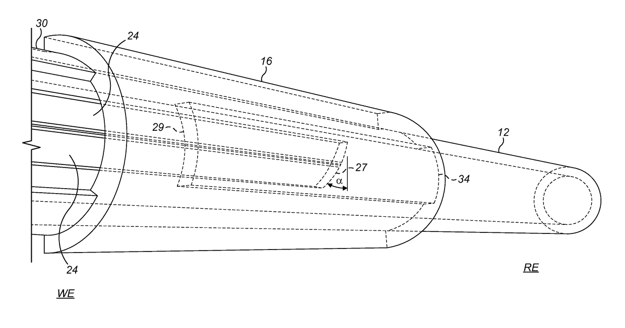
[0115]The three different configurations tested were as follows:[0116]1) The first cutting edge had a square shoulder (90 degrees) and had a relative cutting angle α to the second cutting edge of 15 degrees,[0117]2) The first cutting edge had a square shoulder (90 degrees) and had a relative cutting angle α to the second cutting edge of 30 degrees, and[0118]3) The first cutting edge had 30 degree shoulder and a relative cutting angle α to the second cutting edge of 30 degrees. The r...


PUM


Abstract

There is provided a downhole umbilical release assembly comprising a guillotine arrangement provided by a guillotine alignment sub (12) and a guillotine mandrel (16). The guillotine alignment sub has a first edge (27) over which an umbilical is positioned in a wellbore string. The guillotine mandrel is positioned radially outwardly of the guillotine alignment sub and is arranged to move longitudinally with respect thereto. The guillotine mandrel has a second edge (29) that is arranged to pass over the first edge (27) of the guillotine alignment sub during longitudinal movement of the guillotine mandrel relative to the guillotine alignment sub. This severs an umbilical positioned between the two edges (27,29).

Description

CROSS-REFERENCE TO RELATED APPLICATIONS[0001]This application is a Submission under 35 U.S.C. §371 for U.S. National Stage Patent Application of, and claims priority to, International Application Number PCT / EP2014 / 063698, filed Jun. 27, 2014, entitled “DOWNHOLE UMBILICAL RELEASE ASSEMBLY”, which is related to and claims priority to Norwegian Patent Number NO 336539, filed Jun. 28, 2013, and is also related to and claims priority to Great Britain Application Number GB 1311696.7, filed Jun. 28, 2013, the entire contents of each of which are hereby incorporated herein by reference.TECHNICAL FIELD[0002]The invention relates to an apparatus for releasing a downhole umbilical, and to a corresponding method of releasing a downhole umbilical.INTRODUCTION[0003]Under some circumstances, for example during work-over of an oil and gas well, cutting and retrieval of the drilling or production tubing may be required. In many wells, in particular those on the Norwegian Continental Shelf (NCS), dow...

Claims


Application Information

Patent Timeline
Patent Type & Authority Patents(United States)
IPC IPC(8): E21B29/04E21B29/08E21B29/06
CPCE21B29/04E21B29/08E21B29/06
Inventor SORBO, ESPENLOFTHUS, TOMMY
Owner OIL TOOLS OF NORWAY
Why Eureka
Try Eureka