
Method and an arrangement for controlling fluid flow into a production pipe

a technology of production pipe and fluid flow, which is applied in the direction of sealing/packing, well accessories, and wellbore/well accessories, etc., can solve the problems of the greatest risk, the velocity of oil flow from the reservoir to the pipe, and the pressure in the drainage pipe increases exponentially in the upstream direction, so as to reduce the inflow through the inflow control device, reduce the pressure drop in the drainage pipe, or reduce the effect of the inflow

Active Publication Date: 2017-04-18
DEN NORSKE STATS OLJESELSKAP AS
View PDF11 Cites 3 Cited by
  • Summary
  • Abstract
  • Description
  • Claims
  • Application Information

AI Technical Summary

Benefits of technology

[0014]In one embodiment, when reducing inflow in sections of the drainage pipe where fluid in the formation is at or above its boiling point, the inflow control devices uses the Bernoulli effect and any stagnation pressure created over the movable body. In this way the inflow control devices, depending on the composition and viscosity of the fluid, will close at least partially to reduce inflow locally.
[0029]The temperature responsive device may comprise a sealed expandable means at least partially filled with a material that is arranged to undergo a significant expansion when the temperature in the fluid surrounding the device increases. Preferably, the expansion should be sufficient to substantially or fully close the valve when the temperature in the fluid surrounding the temperature responsive device increases above a predetermined value. Such an expansion can, for instance, be achieved by selecting a material that undergoes a phase change at a predetermined temperature. An example of such a phase change is a liquid which will boil at or above a predetermined temperature. The fluid can comprise a suitable alcohol, an alcohol / water mixture or acetone. The fluid may be selected depending on its boiling point at a predetermined pressure, which pressure is dependent on the pressure acting on the production pipe at the location of the valve, or inflow device. The fluid material may also be selected dependent on where the production pipe is located. For instance, a production pipe located at a depth of 300 meters can be subjected to pressures of 25-30 bar and temperatures of 250-290° C. during normal production conditions. In order to prevent a sudden influx of steam having a higher temperature through the valve, the expandable means can be filled with an alcohol-water mixture that boils at e.g. 280° C. During an undesirable increase of temperature in the fluid flowing through the valve, the expandable means is arranged to expand and cause a displacement of the movable valve body towards its closed position when the temperature of the fluid exceeds said predetermined temperature. In this way, the valve can be closed to prevent boiling or flashing water from entering the production pipe. Flashing or boiling can occur when the differential pressure across the inflow control device is relatively low. If boiling or flashing water is allowed to enter the production pipe, then this causes a “short circuit” of the injection pressure and the production pressure and causes the differential pressure to drop further. This has a negative effect on the efficiency of the drainage process, as outlined above. Other undesirable fluids that can be prevented from entering the production pipe are hot production gases or combustion gases used for increasing the production rate.

Problems solved by technology

A considerable disadvantage with the known devices for oil / and or gas production in highly permeable geological formations is that the pressure in the drainage pipe increases exponentially in the upstream direction as a result of the flow friction in the pipe.
With thin oil zones and highly permeable geological formations, there is further a high risk that of coning, i.e. flow of unwanted water or gas into the drainage pipe downstream, where the velocity of the oil flow from the reservoir to the pipe is the greatest.
Under such conditions, changes in pressure may cause the fluids to flash or boil to produce gas or steam.
This may cause problems should the gas or steam reach the valves used for draining fluid from the reservoir into the production pipe, as many such valves are not able to close to prevent steam or combustion gas from entering the production pipe.
In particular, if the differential pressure is relatively low, ingress of steam or combustion gas can lead to a “short circuit” of the injection pressure and the production pressure.
This will cause the differential pressure to drop even further, which has a negative effect on the efficiency of the drainage process.
In this way, the production pipe will have an undesirable inflow profile along its length.
A break-through of hot fluids, such as hydrocarbons and or water, at temperatures near their respective boiling points can cause the fluid to flash or boil inside the production pipe.
If this occurs upstream of or in a down-hole pump this will have a detrimental effect on the operation of the pump and will result in a limitation of the draw down, that is, the pressure difference between the reservoir pressure and the pressure in the production pipe.
However, the sequence of sections of different diameter creates flow turbulence and prevents the running of work-over tools operated along the outer surface of the production pipe.
None of the above-mentioned, known devices are able to distinguish between and control the inflow of oil, gas or water on the basis of their relative composition and / or quality.
In particular, the known devices are not able to control variations in inflow into the production pipe due to variations of differential pressure caused by temperature variations.
Said valves are also unable to control the effects of fluid flashing or boiling inside the production pipe.

Method used


Image

  • Method and an arrangement for controlling fluid flow into a production pipe
  • Method and an arrangement for controlling fluid flow into a production pipe
  • Method and an arrangement for controlling fluid flow into a production pipe

Examples


first embodiment

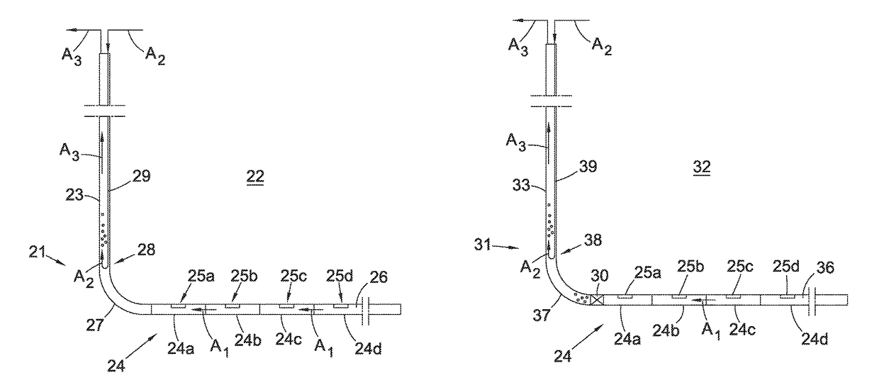
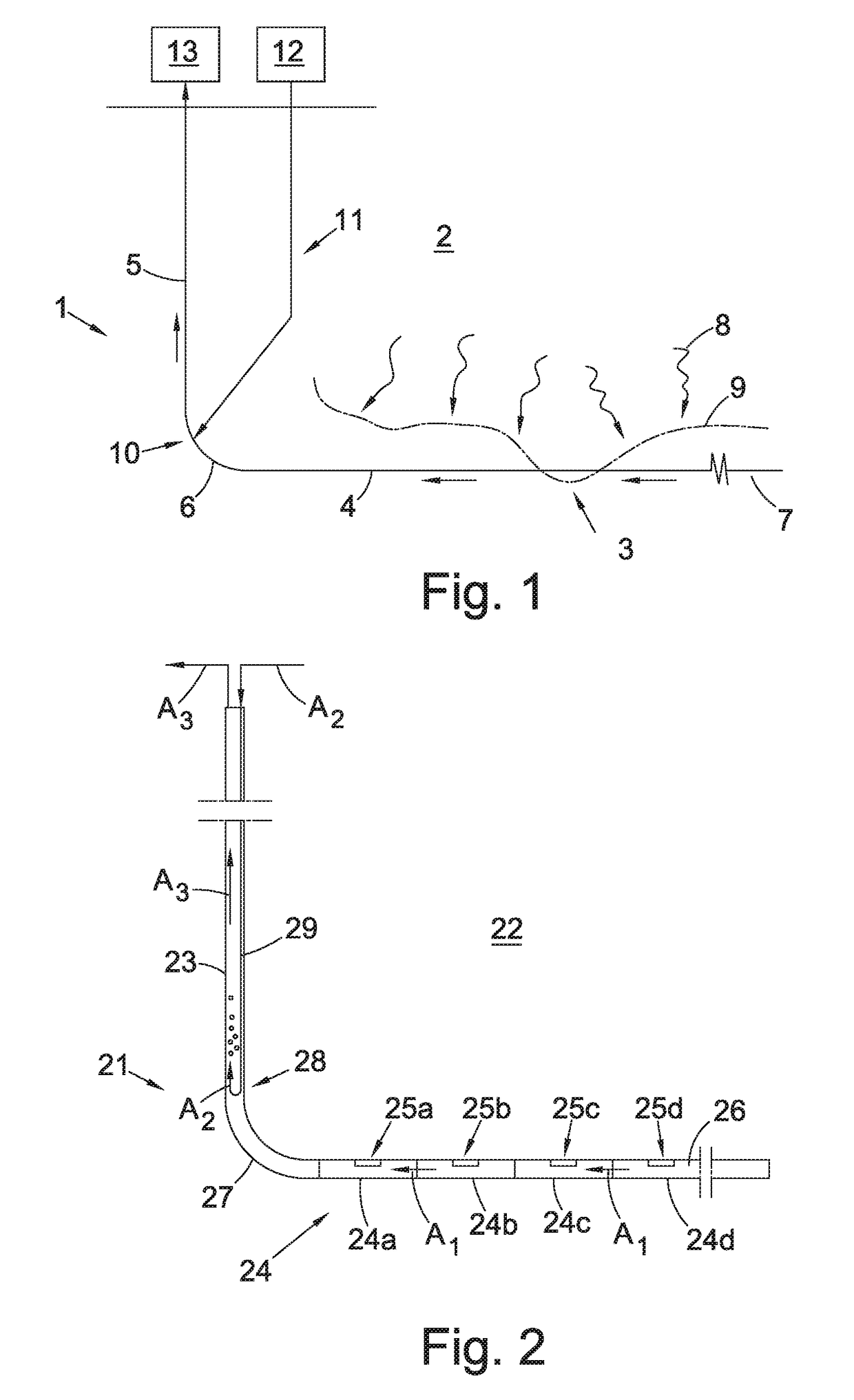
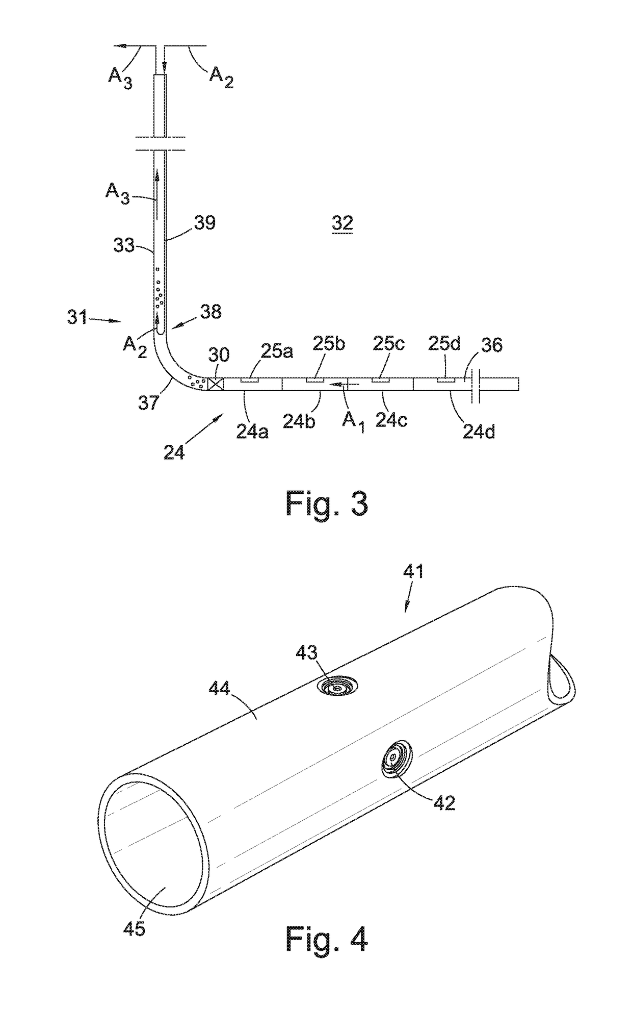
[0043]FIG. 2 shows a schematic view of a production pipe 21 according to the invention. The production pipe 21 is arranged to control the inflow of a fluid from a formation along a length of the production pipe, such as a drainage pipe 24 draining fluid from a reservoir formation 22. The drainage pipe 24 comprises multiple sections 24a, 24b, 24c, 24d (four shown), each provided with one or more inflow control devices 25a, 25b, 25c, 25d (one shown per section) which connects the geological production formation 22 with an internal flow space 26 of the drainage pipe 24. The production pipe 21 further comprises an upper production pipe, or riser 23, for removing or collecting the fluid from the drainage pipe 24, and a heel section 27 connecting the riser 23 and the drainage pipe 24. The drainage pipe 24 extends between the heel 27 and a toe of said production pipe. The direction of flow in the drainage pipe 24 towards the heel 27 is indicated by arrows A1.

[0044]The production pipe also ...

second embodiment

[0048]FIG. 3 shows a schematic view of a production pipe 31 according to the invention. The production pipe 31 is arranged to control the inflow of a fluid from a formation along a length of the production pipe, such as a drainage pipe 34 draining fluid from a reservoir formation 32. The drainage pipe 34 comprises multiple sections 34a, 34b, 34c, 34d (four shown), each provided with one or more inflow control devices 35a, 35b, 35c, 35d (one shown per section) which connects the geological production formation 32 with an internal flow space 36 of the drainage pipe 34. The production pipe 31 further comprises an upper production pipe, or riser 33, for removing or collecting the fluid from the drainage pipe 34, and a heel section 37 connecting the riser 33 and the drainage pipe 34. The drainage pipe extends between the heel 37 and a toe of said production pipe. The direction of flow in the drainage pipe 34 towards the heel 37 is indicated by arrows A1.

[0049]The production pipe also com...


PUM


Abstract

A method of controlling fluid flow into a heavy oil production pipe is disclosed. The method involves reducing inflow into a production pipe locally from hot spots using inflow control devices comprising a movable body provided within a housing. The movable body is arranged to adjust the flow of fluid through the inflow control devices autonomously by exploiting the Bernoulli principle. Inflow into the production pipe remote from said hot spots may be increased using the inflow control devices to increase inflow locally, and draw down in said production pipe may be increased by using an injector to inject a gaseous medium at or downstream of said inflow control devices.

Description

TECHNICAL FIELD[0001]The present invention relates to a method and an arrangement for controlling fluid flow into a heavy oil production pipe provided with inflow control devices. The invention may for example be used to control the mass flow of hydrocarbons into a production pipe in a wellbore.BACKGROUND ART[0002]Devices for recovering of oil and gas from long, horizontal and vertical wells are known from U.S. Pat. Nos. 4,821,801, 4,858,691, 4,574,691 and GB patent publication No. 2169018. These known devices comprise a perforated drainage pipe with, for example, a filter for control of sand around the pipe. A considerable disadvantage with the known devices for oil / and or gas production in highly permeable geological formations is that the pressure in the drainage pipe increases exponentially in the upstream direction as a result of the flow friction in the pipe. Because the differential pressure between the reservoir and the drainage pipe will decrease upstream as a result, the q...

Claims


Application Information

Patent Timeline
Patent Type & Authority Patents(United States)
IPC IPC(8): E21B34/08G05D7/01E21B43/32E21B43/12
CPCE21B43/12E21B34/08E21B43/122E21B43/32G05D7/0146F16K15/02E21B43/24
Inventor MATHIESEN, VIDARAAKRE, HAAVARDGROSTAD, TORSTEIN
Owner DEN NORSKE STATS OLJESELSKAP AS
Learn More