Micro-macro endovascular occlusion device and methodology

a micro-macro endovascular and occlusion technology, which is applied in the field of micro-macro endovascular occlusion devices and methods, can solve the problems of increasing procedure time and potentially cost, detachable balloons being difficult to navigate through blood vessels, and coils being unreliable in their geometry and vascular space filling properties, etc., to achieve the effect of reducing the porosity of the plug wall, increasing the thrombosis rate, and promoting the thrombosis ra

Active Publication Date: 2019-05-28
DEMERITT JOHN S
View PDF7 Cites 13 Cited by
  • Summary
  • Abstract
  • Description
  • Claims
  • Application Information

AI Technical Summary

Benefits of technology

[0009]Another specific object of the present invention to provide an improved vascular occlusion device and / or an associated surgical method wherein an occlusive vascular plug allows for a very large space filling capacity in proportion to the delivery catheter diameter, thereby facilitating large vessel or large aneurysm occlusion, currently not possible with current devices.
[0030]For treating segmental vascular pathology, particularly long segment vascular disease such as an elongated fusiform aneurysm, the present invention contemplates an elongated microcatheter-deliverable vascular plug or occlusion device that is variously expandable to extend completely across segmental vascular pathology in both small and large vessels. This methodology both nearly simultaneously occludes the fusiform aneurysm along its downstream and upstream portions, minimizing the risk of altered hemodynamics and aneurysm rupture during plug deployment, but also prevents downstream aneurysm retrograde reconstitution secondary to flow reversal. A modified solution to the problem of more safely treating segmental vascular pathology, particularly useful for long segment vascular disease such as an elongated fusiform aneurysm, is the placement of successive devices in a strategic manner (endovascular trapping), two such devices being deployed through the same catheter to simultaneously occlude both proximally and distally to the lesion (e.g., a fusiform aneurysm). A first proximal occlusive device is placed to reduce inflow to the lesion, and has a channel or aperture (for instance, a doughnut hole of a spiraling plug configuration) designed to be traversed by same delivery catheter, for the placement of one or more downstream occlusive devices relative to the vascular pathology. The catheter is subsequently withdrawn and repositioned for placement of a second proximal device to close the proximal plug aperture. Alternatively one or more distal and subsequently one or more proximal occlusive devices could be delivered via a microcatheter placed through a 5 French inflated balloon catheter, situated proximal to the vascular pathology in order to eliminate or reduce both flow and intravascular pressure (flow arrest). Therefore, a microcatheter deliverable occlusive device placed coaxially through a 5 French balloon catheter could also solve this problem since the occlusive device or devices could be placed distally and then proximally under the condition of flow arrest. A microcatheter deliverable occlusive device or devices placed through a 5 French balloon catheter (under the condition of flow arrest) could also be useful to create a stable intravascular occlusive construct, in the setting of high flow as might be seen in the setting of an arteriovenous fistula.

Problems solved by technology

Despite these features many coils are often required to occlude blood flow increasing procedure time and potentially cost.
Coils can also be unreliable with regards to their geometry and vascular space filling properties after deployment.
Detachable balloons can be difficult to navigate through blood vessels and can prematurely detach.
Premature balloon detachment can lead to migration and occlusion of normal blood vessels resulting in complications.
Balloons can deflate over time resulting in recurrence of the treated vascular pathology such as has been reported in caroticocavernous fistula.
This device may not immediately lead to thrombosis particularly in patients with clotting disorders, requiring more than one device.
The device can be difficult to deliver and precisely deploy.
In addition the device may not provide long-term occlusion, which has been reported in pulmonary arteriovenous fistula in particular.
The largest MVP microcatheter deliverable covered plug can only treat vessels up to 5 mm in diameter, a distinct disadvantage.
Larger MVP covered plugs require delivery through 4 or 5 French catheters depending on the target vessel size; these larger catheters are often too big and rigid to easily traverse the desired vasculature.
The use of these larger 4 and 5 French catheters to target the more distal vasculature can lead to technical failures, vessel spasm and vascular injury.
The device may not be ideal for high flow situations with possible migration considering it's small footprint and vessel anchoring capabilities.
These larger 5 French diagnostic catheters are often difficult to advance more distally into the primary or secondary aortic branch vessels such as the hepatic artery, splenic artery, renal artery, internal carotid artery and hypogastric artery to name a few.
In addition, microcatheters are advantageous for traversing tortuous anatomy, often difficult or impossible with larger 5 French catheters.
Venous embolization often entails occluding even larger caliber vessels than arteries, often necessitating larger guiding catheters or sheaths for device delivery, such as the uncovered Amplatzer plugs.
This can be difficult and or cumbersome to achieve with current available devices.
Initial occlusion of the downstream portion of the vessel relative to the fusiform aneurysm can result in increased flow and pressure in the aneurysm resulting in rupture.
Although effective this process can be cumbersome when using current methods, particularly for larger aneurysms, requiring multiple coils to fill the aneurysm sac.

Method used


Image

  • Micro-macro endovascular occlusion device and methodology
  • Micro-macro endovascular occlusion device and methodology
  • Micro-macro endovascular occlusion device and methodology

Examples


Embodiment Construction

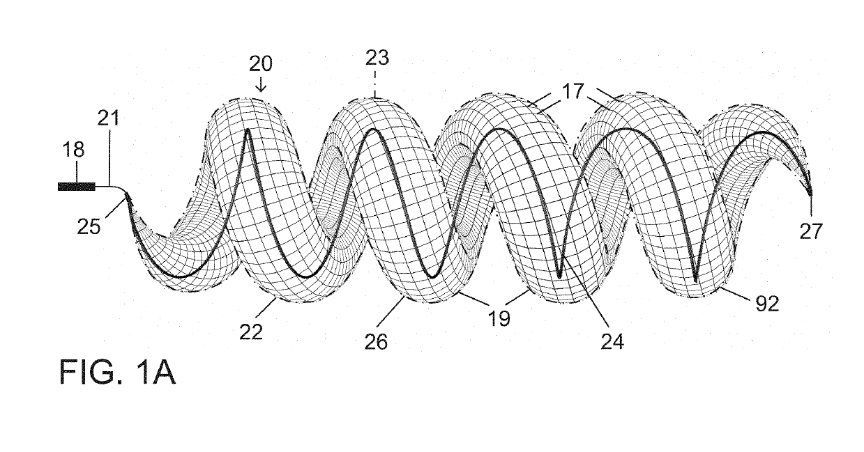
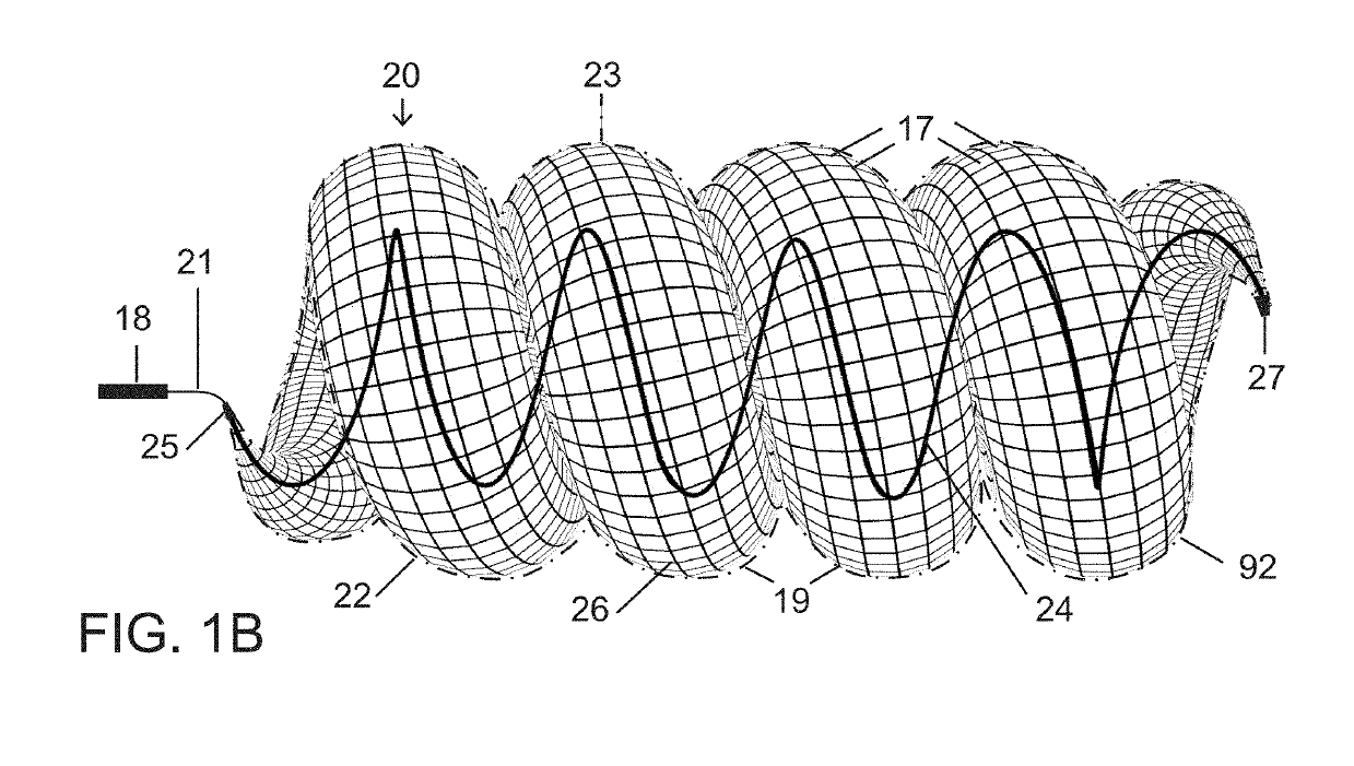
[0065]The present vascular occlusion device or plug, e.g., plug 20 (FIGS. 1A and 1B), is deliverable through a microcatheter 18, which can occlude a wide range of vessel sizes from small to large, currently not possible with available microcatheter deliverable devices. The design allows for the occlusion of vessels both smaller and larger than 5 mm, the current upper limit for a microcatheter deliverable plug.

[0066]In an expanded deployment configuration as shown in FIGS. 1A and 1B, a self-expanding and self-configuring vascular plug or occlusion device 20 takes an expanded form of a three-dimensional spiraling tubular structure 22, optionally covered with an impermeable or partially permeable membrane 23, which allows for large vessel occlusion via microcatheter 18, currently not possible with available devices.

[0067]FIG. 1A shows relative distraction or separation of coiled segments or windings 19 of plug or occlusion device 20 while FIG. 1B shows relative compaction of the coiled...


PUM


Abstract

A vascular plug comprises a superstructure expandable from a collapsed percutaneous insertion configuration to an expanded deployment or use configuration. The superstructure is comprised of both primary and secondary three-dimensional shapes allowing for the occlusion of a wide range of vessel sizes from small to large through a disproportionately small delivery catheter. The plug includes a shape memory element for the generation of radial force and the creation of the larger secondary three-dimensional twisting or helical superstructure as is needed for target vessel occlusion.

Description

BACKGROUND OF THE INVENTION[0001]The present disclosure generally relates to a device and methodology for occluding arterial and venous blood vessels under a variety of pathologic conditions.[0002]Many endovascular devices exist for occluding blood flow including coils, detachable balloons, and most recently expandable mechanical occlusive devices with or without coverings impervious to blood flow. Coils can be covered with fibers or coated with material such as hydrogel to enhance clot formation. Despite these features many coils are often required to occlude blood flow increasing procedure time and potentially cost. Coils can also be unreliable with regards to their geometry and vascular space filling properties after deployment. In addition coils and or clot can easily migrate distally under high flow condition such as arteriovenous fistula in the lungs or elsewhere in the body. Blood vessels occluded by coils can reopen or recanalize as has been reported in pulmonary arterioveno...

Claims


Application Information

Patent Timeline
Patent Type & Authority Patents(United States)
IPC IPC(8): A61B17/12A61B17/00
CPCA61B17/12145A61B17/0057A61B17/1215A61B17/12113A61B17/12172A61B17/12177A61B2017/12127A61B2017/00592A61B2017/00632A61B2017/00867A61B2017/1205A61B17/12031A61B17/12036A61B17/12109A61B17/12122A61B2017/00292A61B17/1214A61B2017/00778A61B2017/12054
Inventor DEMERITT, JOHN S.
Owner DEMERITT JOHN S
Why Eureka
Try Eureka