Reduced stress superback wheel

a superback wheel and stress reduction technology, applied in the direction of blade accessories, machines/engines, combustion engines, etc., can solve the problems of low cycle fatigue failure, repetitive stress on the turbine wheel, and especially severe load, so as to improve the resistance of the turbine wheel to low cycle fatigue and reduce stress. , the effect of easy balan

Active Publication Date: 2017-04-18
BORGWARNER INC
View PDF15 Cites 4 Cited by
  • Summary
  • Abstract
  • Description
  • Claims
  • Application Information

AI Technical Summary

Benefits of technology

[0009]Surprisingly, it was discovered that further improving turbine wheel resistance to low cycle fatigue lie not in complex, cost-adding conventional techniques, but in a further refinement of the overall superback design. With this seemingly small change, it became possible, without additional expense, to provide a turbine wheel that could continue to be easily balanced by conventionally available techniques, yet be less susceptible to stress and low cycle fatigue failure.

Problems solved by technology

This loading is especially severe particularly near the bore.
The turbine wheel is also subjected to repetitive stresses and can experience low cycle fatigue failure.
The commercial turbocharger industry is cost driven.

Method used


Image

  • Reduced stress superback wheel
  • Reduced stress superback wheel
  • Reduced stress superback wheel

Examples


Embodiment Construction

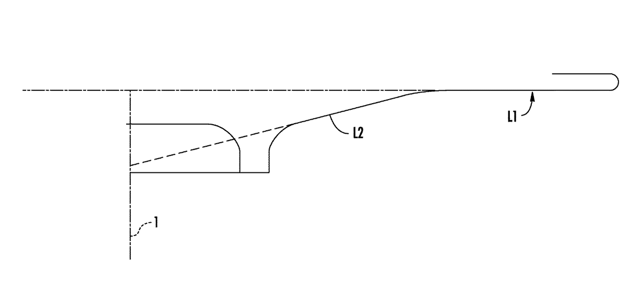
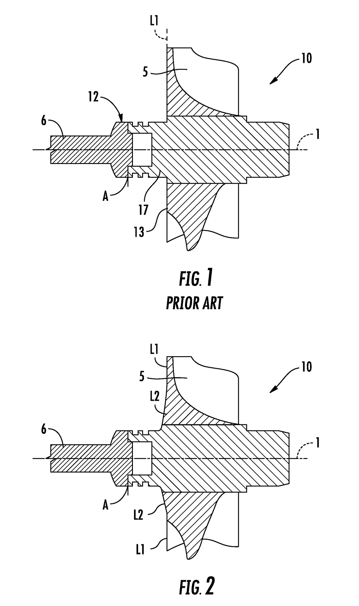
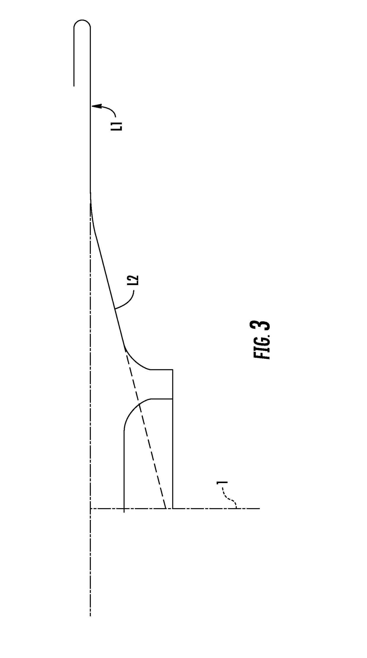
[0015]A conventional turbine wheel (10) is shown in cross section in FIG. 1. Between the backwall (13) of the wheel and the junction (A) between shaft (6) and wheel (10) is a journal or weld boss (17). The wheel is fused to a shaft (6) at junction (A) to form a shaft-and-wheel assembly which rotates about an axis (1).

[0016]Radial inlet flow turbine wheels can be classified into “scalloped backwall” (wherein some hub material is removed from between blades to reduce inertia of the turbine wheel) and “full backwall” (wherein no hub material is removed, providing greater efficiency). The additional material of the full backwall disk however causes elevated stress on the backface of the turbine. These increased stresses can cause a measurable reduction in the low cycle fatigue lifetime, reducing the lifetime below that required in a typical commercial diesel application. The present invention provides the greatest benefit to the full backwall turbine wheel, but can also be applied to sc...


PUM


Abstract

Turbocharger turbine wheels are designed to accelerate rapidly and to rotate at very high RPM. A turbine wheel is provided with improved low cycle fatigue resistance. The wheel can be balanced by conventional methods.

Description

FIELD OF THE INVENTION[0001]The invention relates to stress reduction in a wheel designed to accelerate rapidly and to rotate at very high RPM, such as a turbine wheel of a turbocharger.BACKGROUND OF THE INVENTION[0002]Turbochargers extract energy from a vehicle exhaust to drive a compressor to deliver air at high density to the engine intake, allowing more fuel to be combusted, thus boosting the engine's horsepower. Tighter regulation of engine exhaust emissions has led to an interest in boost devices capable of delivering ever higher pressure ratios. One way to achieve this is to drive the compressor wheel at higher tip speeds, typically translating to 80,000 RPM to 300,000 RPM, depending upon the diameter of the compressor wheel. Not only high rotational speeds, but also shaft forces to rapidly accelerate the compressor wheel, create high tensile loading of the compressor wheel. This loading is especially severe particularly near the bore. It is conventional to reinforce the back...

Claims


Application Information

Patent Timeline
Patent Type & Authority Patents(United States)
IPC IPC(8): F01D5/02F01D5/04F01D5/14
CPCF01D5/048F01D5/025F01D5/141F05D2220/40F05D2230/232F01D5/26F02B37/00F02B39/00Y02T10/12
Inventor CHANDRAMOHANAN, RAJMOHAN T.ANSCHEL, PAUL K.
Owner BORGWARNER INC
Why Eureka
Try Eureka