Capacitive sensing device and method that reduces influence from transient environmental changes
a sensing device and sensor technology, applied in the field of capacitive sensing devices and methods, can solve the problems of easy affecting, misjudge the change of increase or decrease in the capacitive value of the sensing point, so as to achieve the effect of improving the response speed of temperature change and maintaining the accuracy of the signal-reading process over tim
- Summary
- Abstract
- Description
- Claims
- Application Information
AI Technical Summary
Benefits of technology
Problems solved by technology
Method used
Image
Examples
first embodiment
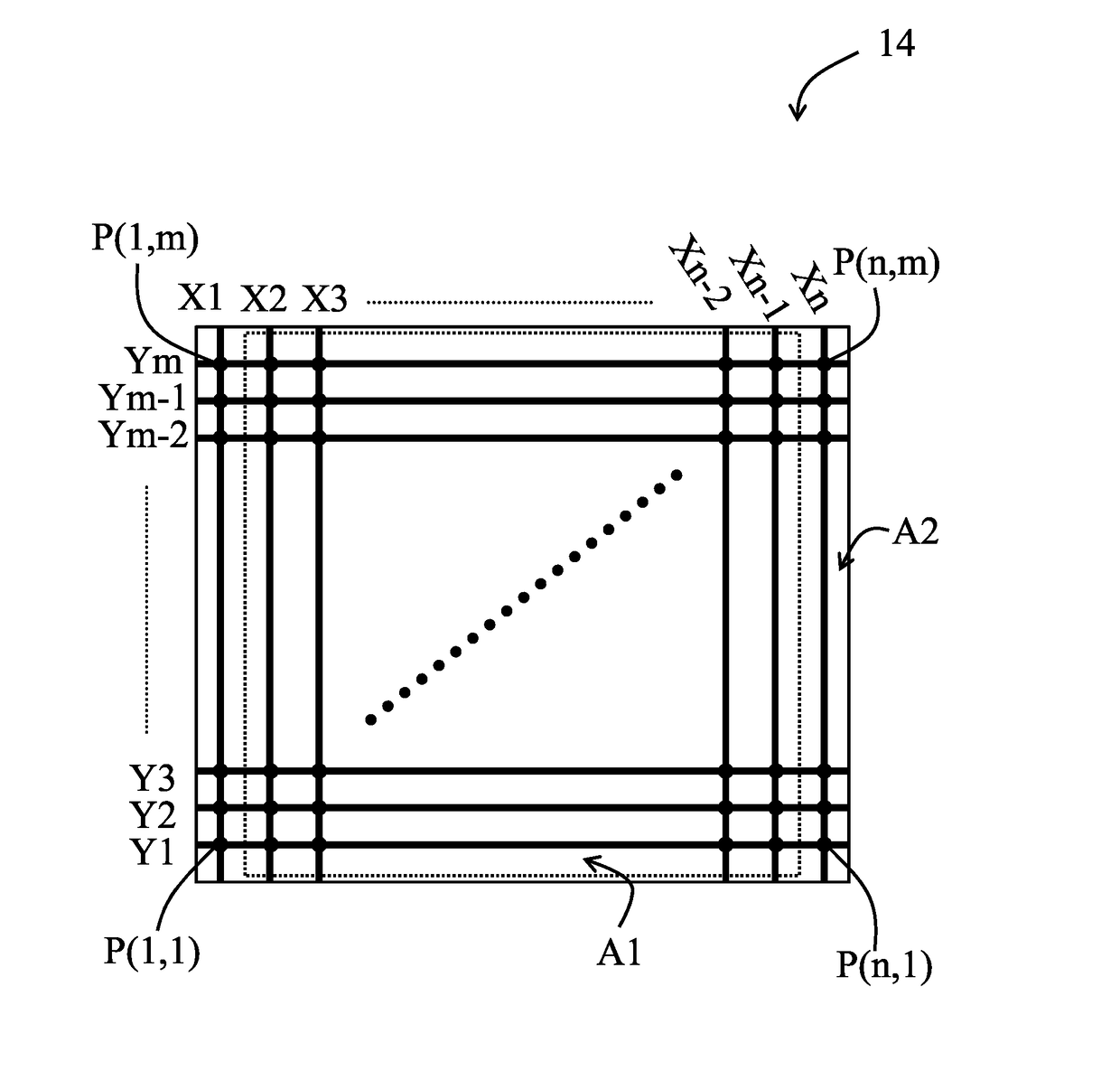
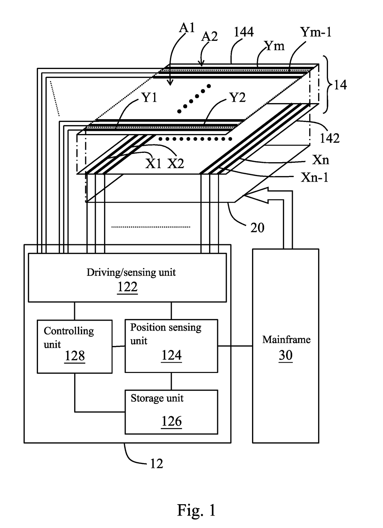
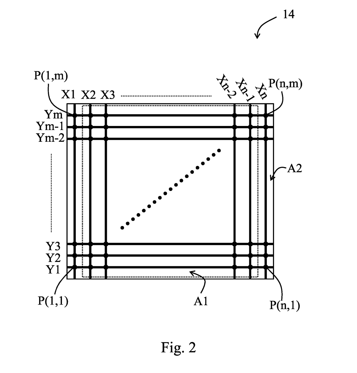
[0060]Details about the measuring step for measuring the first measured values in the step S11 and the step S53 and the measuring step for measuring the second measured values in the step S57 are further described. Referring to FIG. 1, FIG. 2, and FIG. 6, in the measuring step for measuring the first measured values in the step S11 and the step S53 and the measuring step for measuring the second measured values in the step S57, the reference points are a 2*1 number of sensing points located at each corner of the array (for example, P(1,1) and P(2,1), P(1,m) and P(2,m), P(n,1) and P(n-1,1), and P(n,m) and P(n-1,m)), and the driving / sensing unit 122 drives two first electrodes X1, X2 located at a first side of the array and two first electrodes Xn-1, Xn located at a second side of the array (step S71). Wherein, the first side is opposite to the second side.
[0061]Next, the driving / sensing unit 122 measures one second electrode Y1 located at a third side of the array and one second elec...
second embodiment
[0063]In the measuring step for measuring the first measured values in the step S11 and the step S53 and the measuring step for measuring the second measured values in the step S57, the reference points are one sensing point located at each corner of the array (for example, P(1,1), P(1,m), P(n,1), and P(n,m)), and the driving / sensing unit 122 drives one first electrode X1 located at the first side of the array (i.e., the leftmost first electrode) and one first electrode Xn located at the second side of the array (i.e., the rightmost first electrode) (step S71). Next, the driving / sensing unit 122 measures one second electrode Ym located at the third side of the array (i.e., the topmost second electrode) and one second electrode Y1 located at the fourth side of the array (i.e., the bottommost second electrode) to obtain the present measured values of the reference points (step S73).
third embodiment
[0064]In the measuring step for measuring the first measured values in the step S11 and the step S53 and the measuring step for measuring the second measured values in the step S57, the reference points are a 1*2 number of sensing points located at each corner of the array (for example, P(1,1) and P(1,2), P(1,m) and P(1,m-1), P(n,1) and P(n,2), and P(n,m-1) and P(n,m)), and the driving / sensing unit 122 drives one first electrode X1 located at the first side of the array and one first electrode Xn located at the second side of the array (step S71). Next, the driving / sensing unit 122 measures two second electrodes Ym, Ym-1 located at the third side of the array and two second electrodes Y1, Y2 located at the fourth side of the array to obtain the present measured values of the reference points (step S73).
PUM
 Abstract
Description
Claims
Application Information
 - R&D
- Intellectual Property
- Life Sciences
- Materials
- Tech Scout
- Unparalleled Data Quality
- Higher Quality Content
- 60% Fewer Hallucinations
Browse by: Latest US Patents, China's latest patents, Technical Efficacy Thesaurus, Application Domain, Technology Topic, Popular Technical Reports.
© 2025 PatSnap. All rights reserved.Legal|Privacy policy|Modern Slavery Act Transparency Statement|Sitemap|About US| Contact US: help@patsnap.com


