

Operating switch
a technology of operating switch and tilt angle, which is applied in the direction of electric switches, emergency actuators, electrical apparatus, etc., can solve the problems of difficult to adjust the scroll speed of the display or the moving speed of the selected icon, and achieve the effect of accurately determining the tilt angle of the operating body and accurately determining the tilt angl
- Summary
- Abstract
- Description
- Claims
- Application Information
AI Technical Summary
Benefits of technology
Problems solved by technology
Method used
Image

Examples
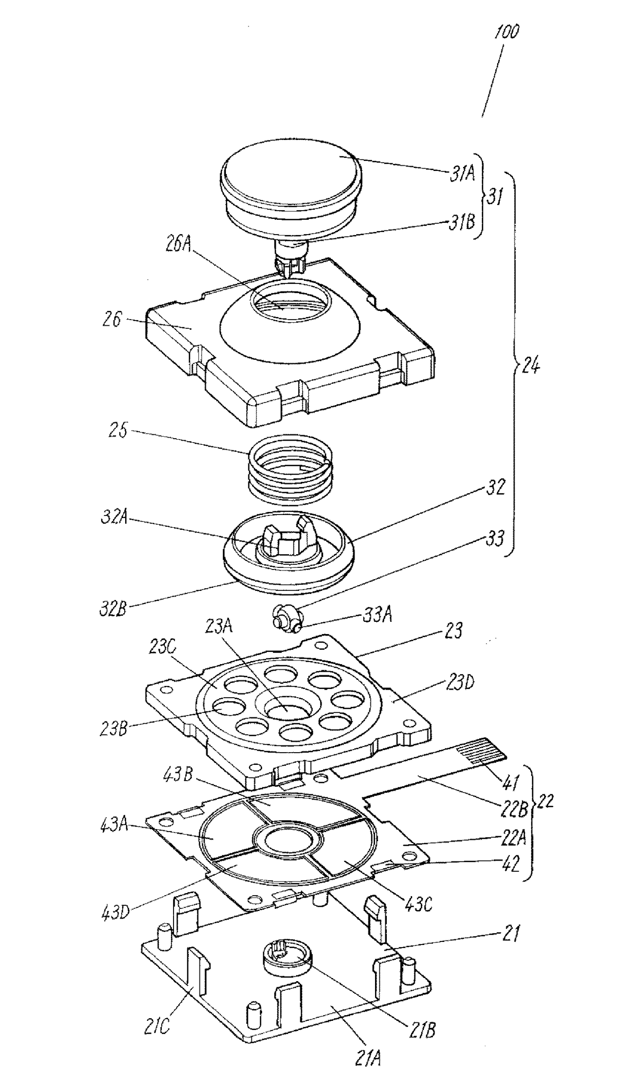
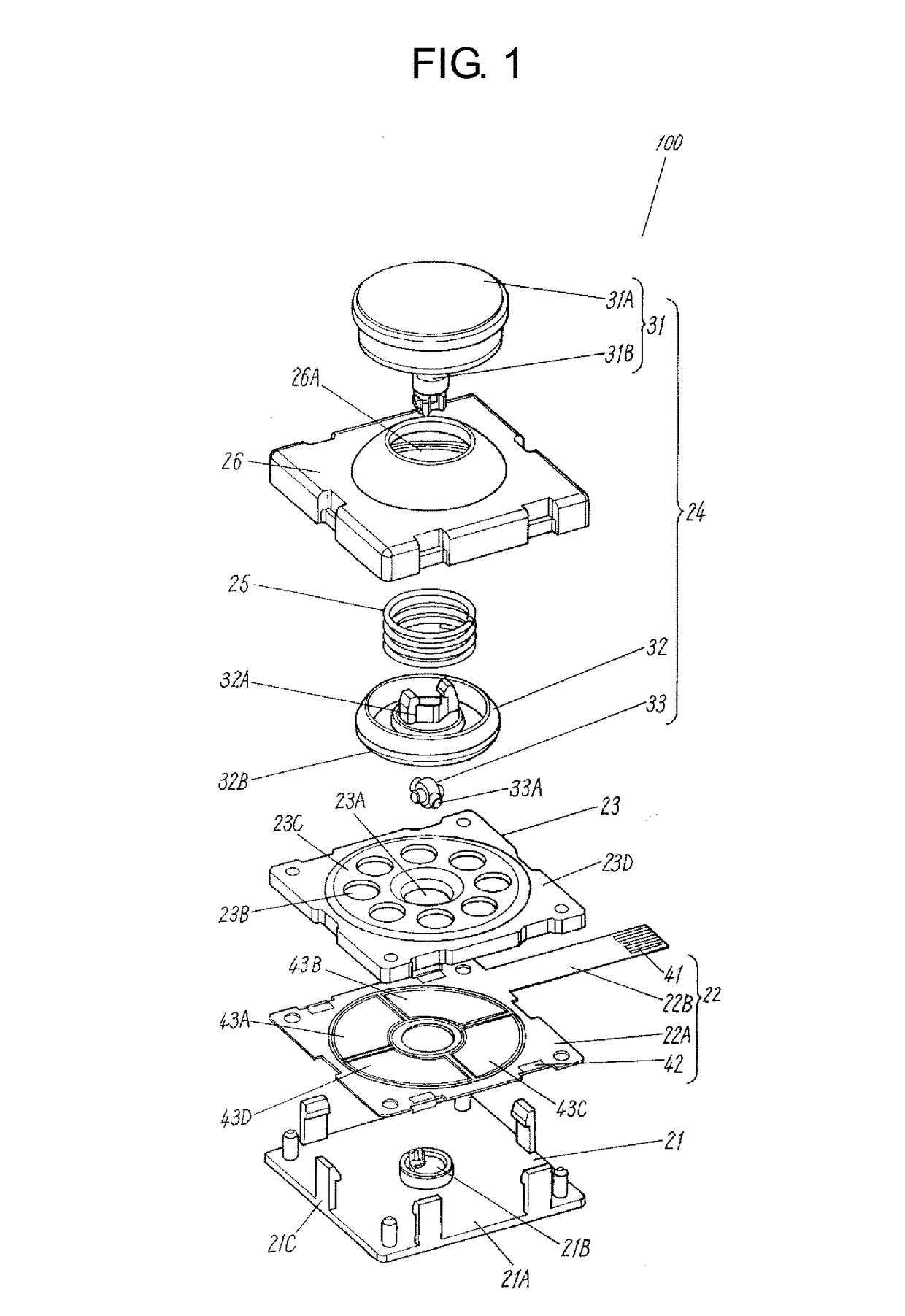
case 26
[0044]Upper case 26 is made of insulating resin, includes circular opening 26A at its center, and shapes like a box of which underside is open. Materials for lower case 21, operating body 24, and upper case 26 can be selected from, e.g. polyacetal, nylon, polycarbonate, and acrylonitrile butadiene styrene (ABS) resin.
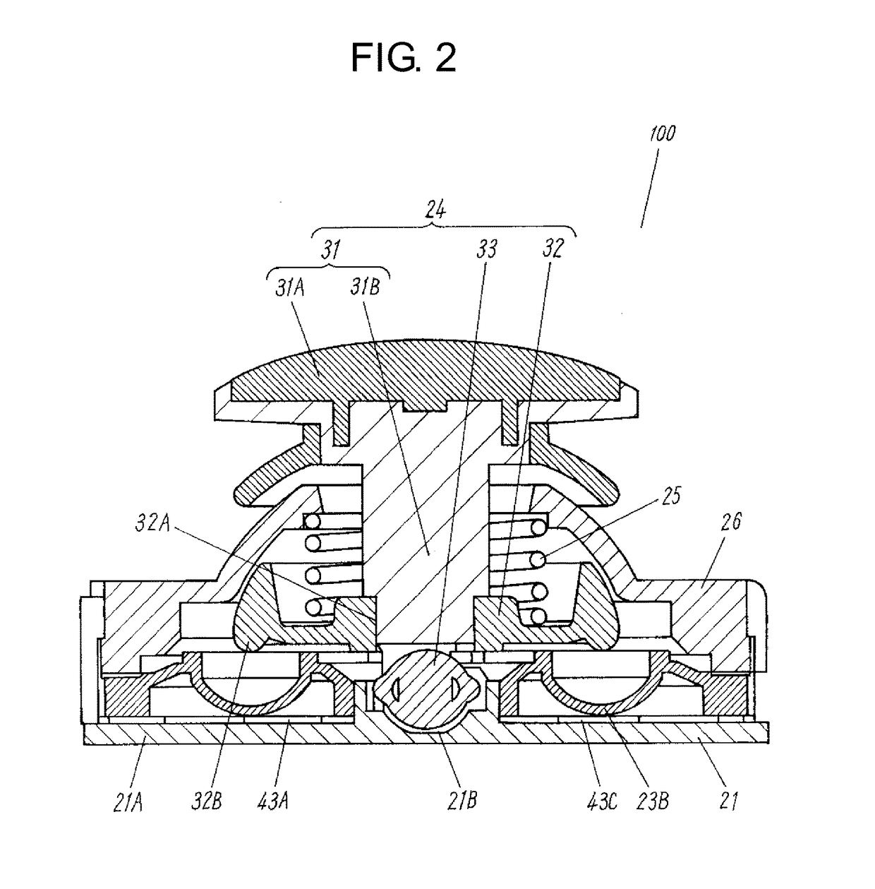
[0045]The insulating layer (not shown) disposed on the top face of fixed electrodes 43A-43D has been described in this embodiment as disposed on fixed electrode body 22 side; however, the insulating layer can be disposed on movable electrode body 23 side. It is easier to form the insulating layer on fixed electrode body 22 side rather than on movable electrode body 23 side.
[0046]Fixed electrode body 22 has been described in this embodiment as employing a flexible printed circuit board; however, it can employ a rigid board such as a glass epoxy board.
[0047]A method for assembling multi-directional operating switch 100 is demonstrated hereinafter. First, place fixed elect...
PUM
 Abstract
Description
Claims
Application Information