Displacement of scraping rollers

a scraping roller and dislocation technology, applied in the field of dislocation of scraping rollers, can solve the problems of dull teeth or scraping edges, and achieve the effect of convenient closing

Inactive Publication Date: 2017-04-25
EIKON TECH HLDG
View PDF14 Cites 1 Cited by
  • Summary
  • Abstract
  • Description
  • Claims
  • Application Information

AI Technical Summary

Benefits of technology

[0006]By displacing at least one of the scraping rollers of the apparatus but preferably more, such as all scraping rollers of the scraping device away from the mandrel, the scraping rollers become much more accessible for manual interaction such as for replacing the scraping rollers.
[0007]It is particularly advantageous that the displacement means are arranged for displacement of the at least one scraping roller in a substantially rectilinear movement, i.e. in a substantially straight movement along the axis of rotation of the individual roller. In this manner, the least space is required within the interior of the apparatus to give room for displacement of the scraping roller or rollers and it is in particular advantageous where a cover is provided for enclosing the scraping device and a part of the mandrel and taking up debris that is removed from the skin side of the pelt by the scraping rollers. When the movement of the scraping roller or rollers is rectilinear in the direction of the axis of rotation of the individual roller or rollers, the openings in the cover for allowing the scraping rollers to extend into the interior of the cover, the compartment, to be of a restricted size and easier to close by means of lids that surround the drive shafts on which the scraping rollers are attached and are removed and installed in place together with the scraping rollers.

Problems solved by technology

Scraping rollers of apparatuses for processing of the skin side of pelts of fur animals, such as mink or foxes are worn during use so that the scraping edges or teeth become dull.

Method used


Image

  • Displacement of scraping rollers
  • Displacement of scraping rollers
  • Displacement of scraping rollers

Examples


Embodiment Construction

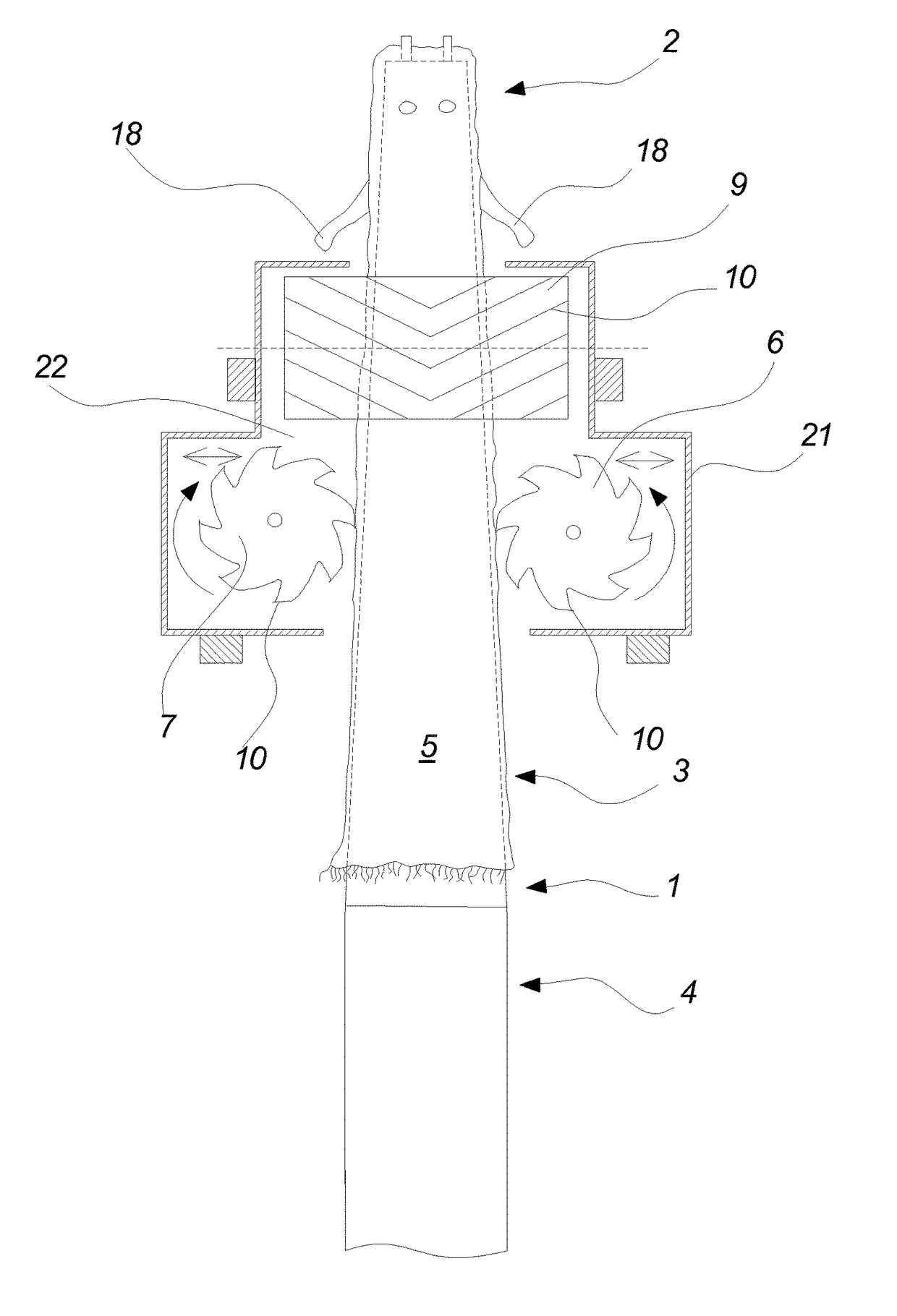
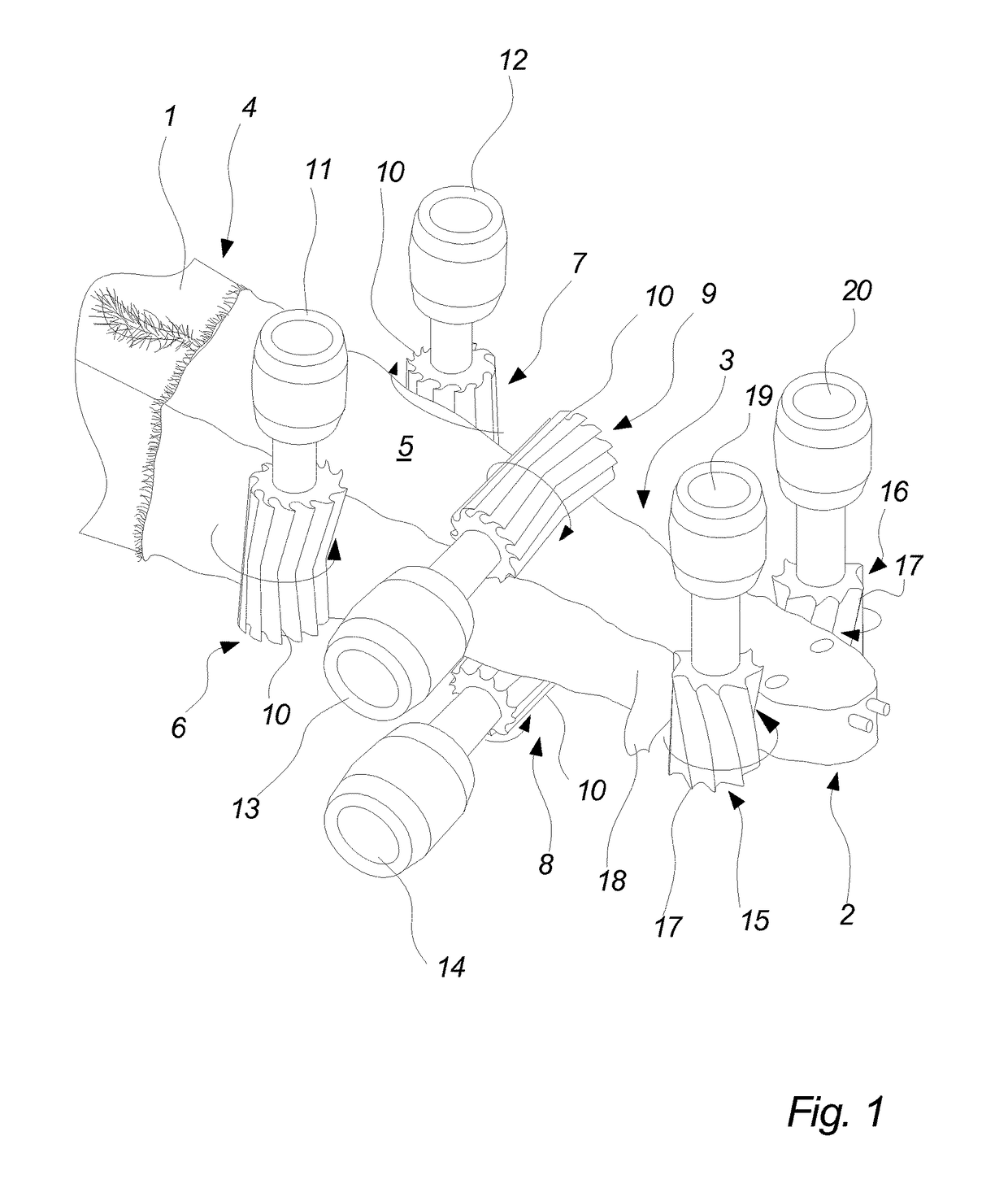
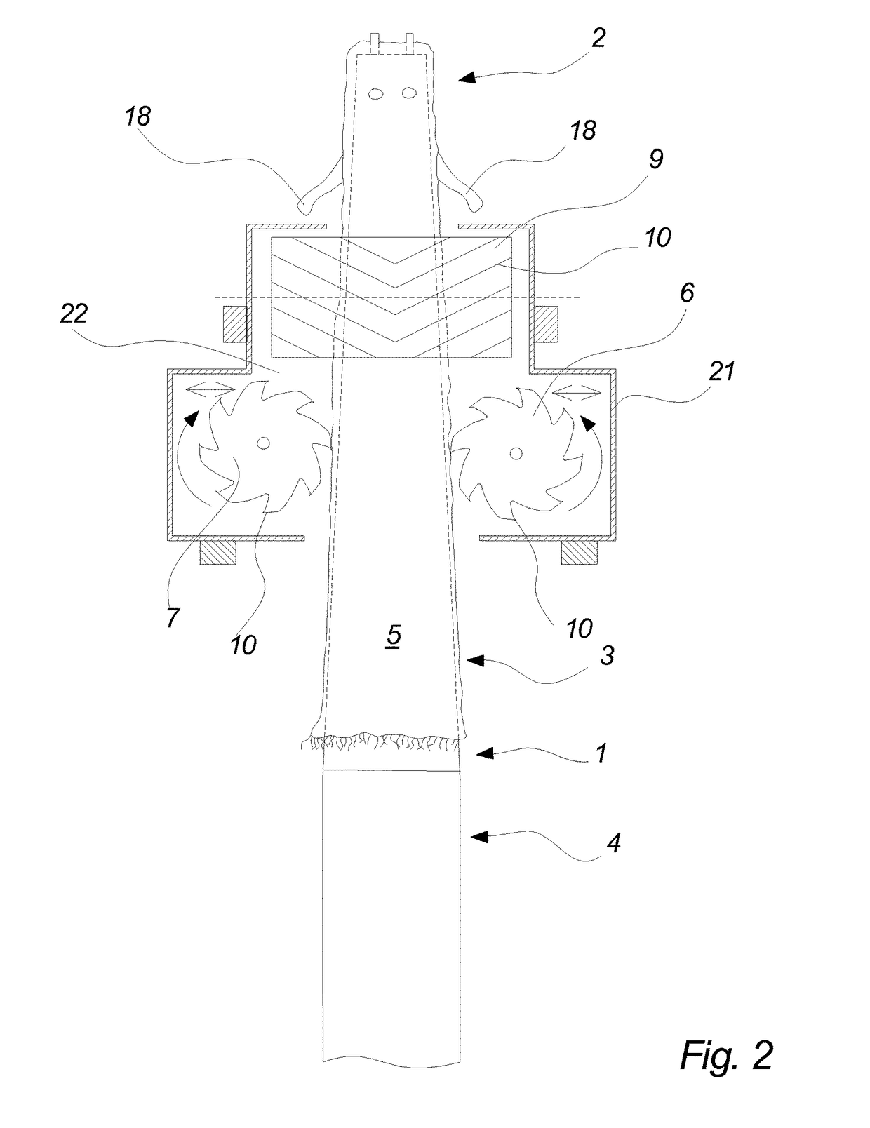
[0024]The apparatus of the present invention of which some parts only are shown in FIG. 1 comprises an mandrel 1 which is tapering towards a thinner, free end 2 from which the tubular pelt 3 is drawn over the mandrel and a thicker end 4 which is connected to and supported by the frame of the apparatus (not shown) where the drive means are arranged for driving the mandrel 1 in the longitudinal direction thereof during operation of the apparatus for scraping the skin side 5 of the pelt 3 arranged on the mandrel 1.

[0025]The apparatus comprises two sets of primary scraping rollers 6, 7, 8, 9 having V-shaped teeth 10 and drive means 11, 12, 13, 14 for driving the scraping rollers 6, 7, 8, 9 in a rotation about corresponding axes. The apparatus further comprises biasing means (not shown) for biasing the teeth 10 of the scraping rollers 6, 7, 8, 9 towards the skin side 5 of the pelt 3 during operation of the apparatus. The apparatus shown in FIG. 1 further comprises a set of secondary scra...


PUM

PropertyMeasurementUnit
distanceaaaaaaaaaa
distanceaaaaaaaaaa
displacementaaaaaaaaaa

Abstract

An apparatus is disclosed for processing the skin side (5) of a tubular pelt (3), the apparatus comprising an elongated tapering mandrel (1) for supporting the pelt with its skin side turned outwards, a scraping device comprising a first set of primary scraping roller (6, 7) arranged on opposing sides of the mandrel and a second set of primary scraping rollers (8, 9) arranged on other opposing sides of the mandrel, the scraping device further comprising primary rotation means (6, 7, 8, 9) for rotating said primary scraping rollers during processing of a pelt so as to engage a skin side of the pelt, moving means for conducting a relative movement between the scraping device and the mandrel in the longitudinal direction of the mandrel, and displacement means for displacing at least one scraping roller in the direction of the axis of rotation of said scraping roller.

Description

[0001]This application claims the benefit under 35 U.S.C. §371 of International Application No. PCT / EP2013 / 067106, filed Aug. 16, 2013, which claims the benefit of Danish Patent Application No. PA 2012 70525, filed Aug. 30, 2012 which are incorporated by reference herein in their entirety.[0002]The present invention relates to an apparatus for processing the skin side of a tubular pelt from a fur animal, in particular from a mink.BACKGROUND[0003]Scraping rollers of apparatuses for processing of the skin side of pelts of fur animals, such as mink or foxes are worn during use so that the scraping edges or teeth become dull. For that reason, it is necessary to replace the scraping rollers in the apparatus after a certain number of pelts have been processed.[0004]It is an objective of the present invention to provide an apparatus which facilitates the replacing of the scraping rollers.BRIEF DESCRIPTION OF THE INVENTION[0005]The above objective is achieved with the present invention whic...

Claims


Application Information

Patent Timeline
Patent Type & Authority Patents(United States)
IPC IPC(8): C14B1/10C14B15/00C14B17/02
CPCC14B15/00C14B17/02C14B1/10
Inventor PEDERSEN, KURT
Owner EIKON TECH HLDG
Why Eureka
Try Eureka