Antenna isolation shrouds and reflectors

a technology of isolation shrouds and reflectors, applied in the direction of antennas, antenna details, antenna couplings, etc., can solve the problems of not being economically feasible to lay new fibers, not being able to extend the reach of optical fibers to sparsely populated areas, and limit the application of optical fibers, so as to prevent the spread of rf energy

Active Publication Date: 2017-04-25
UBIQUITI INC
View PDF129 Cites 26 Cited by
  • Summary
  • Abstract
  • Description
  • Claims
  • Application Information

AI Technical Summary

Problems solved by technology

However, there are limitations to the application of optical fibers.
Because laying optical fibers in the field can require a large initial investment of time and material, it is not cost effective to extend the reach of optical fibers to sparsely populated areas, such as rural regions or other remote, hard-to-reach areas.
Moreover, in many scenarios in which a business may want to establish point-to-point links among multiple locations, it may not be economically feasible to lay new fibers.
However, currently available wireless technologies for long-range, point-to-point (or point-to-multipoint) connections of electromagnetic signals encounter many problems, such as limited range and poor signal quality.
Conventional radio devices, including radio devices having parabolic reflectors, suffer from a variety of limitations and problems.
Other difficulties and limitations include aligning with an appropriate receiver, monitoring and switching between transmitting and receiving functions, avoiding interference (including reflections and spillover from adjacent radios / antennas), loss of signal, mechanical damage, expense, and complying with regulatory requirements without negatively impacting function.

Method used


Image

  • Antenna isolation shrouds and reflectors
  • Antenna isolation shrouds and reflectors
  • Antenna isolation shrouds and reflectors

Examples


Embodiment Construction

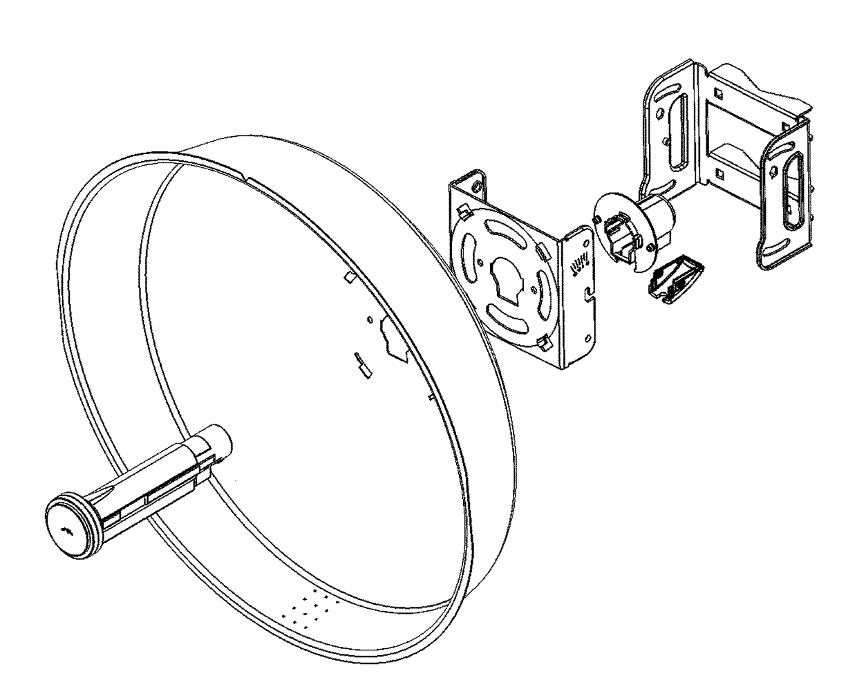
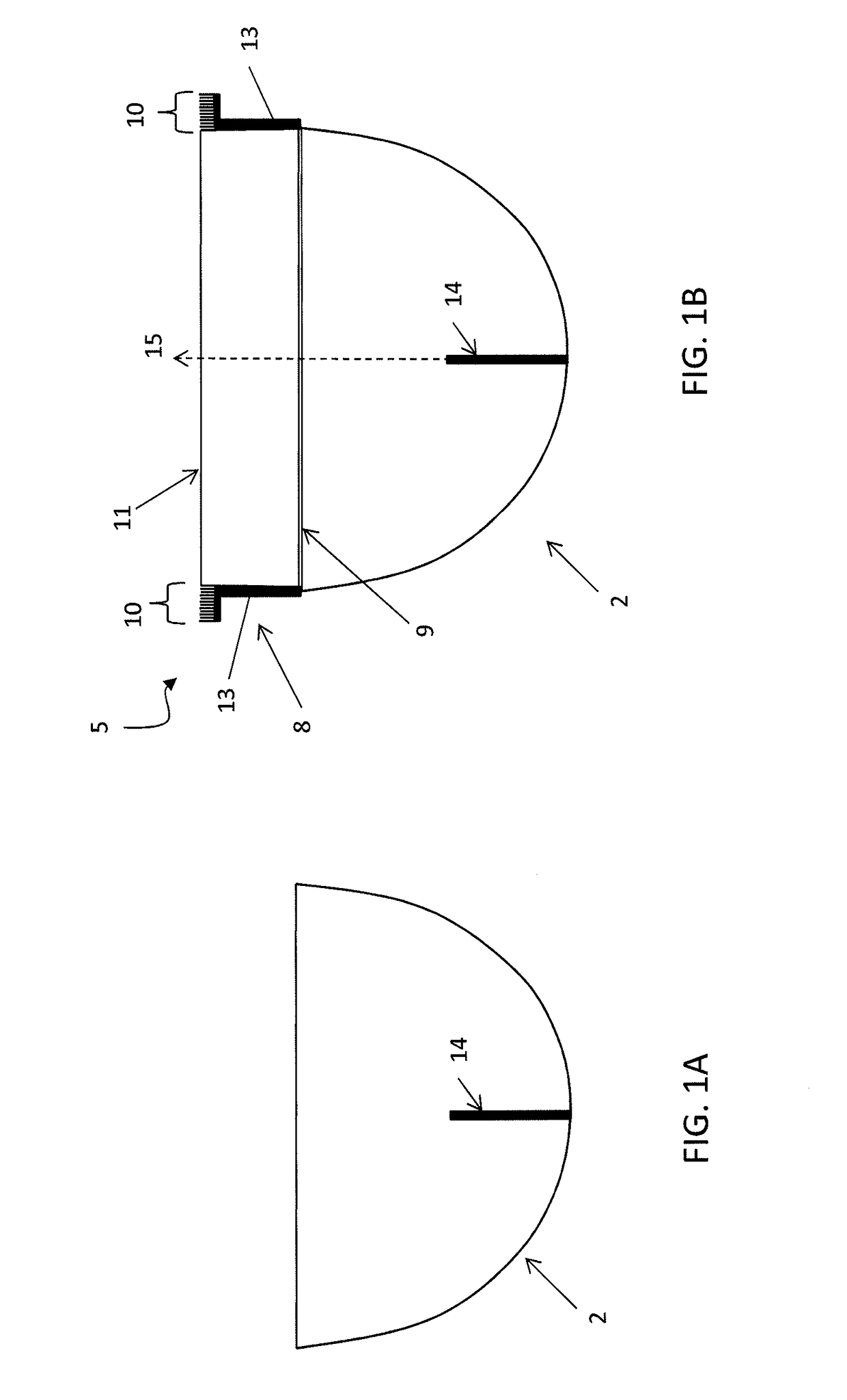
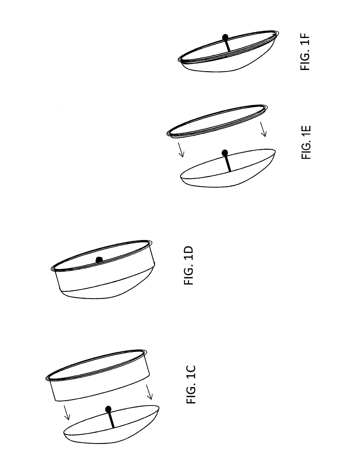
[0124]Described herein are apparatuses (including devices and systems) including choke shrouds and methods for improving and protecting radio devices and systems, such as those used for high-speed, long-range wireless communication, using choke shrouds. In general, these apparatuses may include a shroud component extending an opening of an antenna reflector (e.g., parabolic reflector) and a choke boundary portion extending from a distal end of the shroud component (where the choke is oriented perpendicular to the central axis of the shroud portion). The choke boundary portion may be mounted on the shroud portion so that the choke boundary and shroud are held in a fixed relationship with each other. The shroud may be adapted to connect with an open end of a reflector (such as a parabolic reflector) and hold the choke boundary region relative to the reflector to attenuate RF electromagnetic signals to and / or from an antenna when it is coupled with the reflector. In some variations, th...


PUM


Abstract

Shroud isolation, including choke shroud isolation, apparatuses for wireless antennas for point-to-point or point-to-multipoint transmission / communication of high bandwidth signals, and integrated reflectors including a shroud or choke shroud. A choke shroud systems may include a cylindrical body with an isolation choke boundary at the distal opening to attenuate electromagnetic signals to, from, or within the antenna. The isolation choke boundary region may have ridges that may be tuned to a band of interest. The isolation choke boundary may provide RF isolation when used near other antennas.

Description

CROSS REFERENCE TO RELATED APPLICATIONS[0001]This patent application claims priority to U.S. Provisional Patent Application No. 62 / 063,911, filed Oct. 14, 2014, titled “SIGNAL ISOLATION SHROUD FOR ANTENNA,” and U.S. Provisional Patent Application No. 62 / 202,742, filed Aug. 7, 2015, titled “SIGNAL ISOLATION SHROUDS AND REFLECTORS INCLUDING SIGNAL ISOLATION SHROUDS FOR ANTENNA,” each of which is herein incorporated by reference in its entirety.[0002]This patent application may be related to U.S. patent application Ser. No. 14 / 486,992, filed Sep. 15, 2014, titled “DUAL RECEIVER / TRANSMITTER RADIO DEVICES WITH CHOKE,” now Publication No. US-2015-0002357-A1, which claimed priority as a continuation of U.S. patent application Ser. No. 14 / 170,441, filed Jan. 31, 2014, titled “DUAL RECEIVER / TRANSMITTER RADIO DEVICES WITH CHOKE,” now U.S. Pat. No. 8,836,601, which claimed priority as a continuation-in-part to U.S. patent application Ser. No. 13 / 843,205, filed Mar. 15, 2013, titled “RADIO SYST...

Claims


Application Information

Patent Timeline
Patent Type & Authority Patents(United States)
IPC IPC(8): H01Q1/52H01Q1/12H01Q19/02
CPCH01Q1/1228H01Q1/125H01Q1/523H01Q19/022H01Q1/242
Inventor LEE, JUDESANFORD, JOHN R.PERA, ROBERT J.
Owner UBIQUITI INC
Why Eureka
Try Eureka