Control method for reducing torque ripple in an electrical machine

a control method and technology for electrical machines, applied in the field of electric machines, can solve the problems of torque ripple, complicated control of electrical machines, limiting factors in the application of electrical machines, etc., and achieve the effects of reducing torque ripple, simple current regulation algorithm, and convenient use of standard inverter topology

Active Publication Date: 2017-04-25
GENERAL ELECTRIC CO
View PDF15 Cites 0 Cited by
  • Summary
  • Abstract
  • Description
  • Claims
  • Application Information

AI Technical Summary

Benefits of technology

[0007]According to another embodiment, a method of controlling torque ripple in an electrical machine, wherein the electrical machine includes a field winding for creating nominally constant field current using DC current and an armature winding for creating a rotating magnetic field using AC current, the method comprises superimposing a spatially varying current component on to the DC current of the field winding, thereby reducing torque ripple in the electrical machine.

Problems solved by technology

A limiting factor in the application of electrical machines (e.g., switched reluctance motors (SRMs), flux switching motors (FSMs), or wound-field synchronous motors) is the torque ripple produced by interaction of the stator and rotor magnetic fields as the machine rotates.
Control of the electrical machine is complicated by the spatial and magnetic nonlinearities inherent to the machine.

Method used


Image

  • Control method for reducing torque ripple in an electrical machine
  • Control method for reducing torque ripple in an electrical machine
  • Control method for reducing torque ripple in an electrical machine

Examples


Embodiment Construction

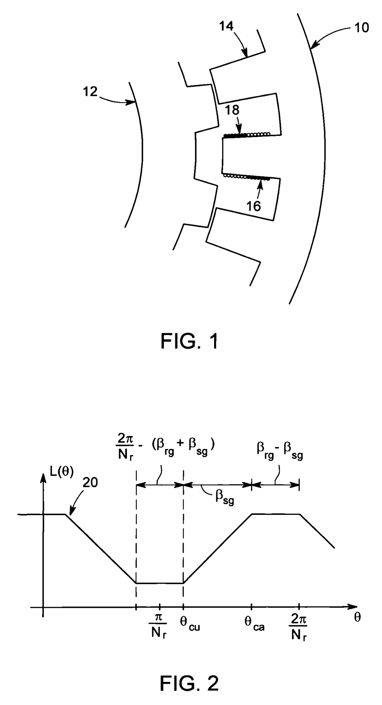
[0022]FIG. 1 is an axial view illustrating one portion of stator and rotor laminations 10, 12 for an electrical machine, according to one embodiment. The stator laminations 10 comprise a plurality of teeth 14. One or more short-pitch, concentrated windings are wound around each of the plurality of stator teeth 14. The short-pitch, concentrated windings may include an AC winding 16 and a DC winding 18, according to one embodiment. The term “short pitch, concentrated” as used herein means that each stator winding wraps around only one stator tooth 14. The rotor laminations 12 are devoid of windings or permanent magnets and the rotor is comprised of salient magnetic poles. The number of salient poles on the stator and rotor will necessarily be different to support torque production at all rotor positions. The stator and rotor poles are symmetrically displaced in space. The AC winding 16 on each stator tooth is associated with a particular phase winding. The magnetic polarity of the AC ...


PUM


Abstract

A method of controlling torque ripple in an electrical machine that includes a field winding for creating nominally constant field current using DC current and an armature winding for creating a rotating magnetic field using AC current, calls for superimposing a spatially varying current component on to the DC current of the field winding. Other methods are also disclosed that are suitable for electrical machines that have a winding that is excited with nominal DC current including SRMs, FSMs, and wound-field synchronous motors.

Description

CROSS REFERENCE TO RELATED APPLICATIONS[0001]This Continuation-In-Part (C.I.P.) application claims priority to the Jun. 9, 2014 filing date of U.S. application Ser. No. 14 / 299,116 (Entitled: CONTROL METHOD FOR REDUCING TORQUE RIPPLE IN SWITCHED RELUCTANCE MOTORS, which, in turn, claims priority under 35 U.S.C. §119(e)(1) of provisional application Ser. No. 61 / 942,199, filed Feb. 20, 2014 . Both references are incorporated herein in their entirety.BACKGROUND[0002]The subject matter of this disclosure relates generally to electrical machines, and more particularly, to a control method for reducing torque ripple in electrical machines.[0003]A limiting factor in the application of electrical machines (e.g., switched reluctance motors (SRMs), flux switching motors (FSMs), or wound-field synchronous motors) is the torque ripple produced by interaction of the stator and rotor magnetic fields as the machine rotates. (While all electrical machines have this issue, aspects of this invention r...

Claims


Application Information

Patent Timeline
Patent Type & Authority Patents(United States)
IPC IPC(8): H02P6/10H02P25/098H02P25/092
CPCH02P6/10H02P25/092H02P25/098
Inventor TORREY, DAVID ALLAN
Owner GENERAL ELECTRIC CO
Why Eureka
Try Eureka