Rotating electric machine apparatus

a technology of electric machines and rotating motors, applied in the direction of electronic commutator control, electronic commutator control, control systems, etc., can solve the problems of increasing torque ripple in the rotating electric machine, and achieve the effect of enhancing the reliability of the first neutral point switch and the reliability of the second neutral point switch

Active Publication Date: 2020-05-05
DENSO CORP
View PDF5 Cites 0 Cited by
  • Summary
  • Abstract
  • Description
  • Claims
  • Application Information

AI Technical Summary

Benefits of technology

[0009]The main object of the present disclosure is to provide a rotating electric machine apparatus that is capable of reducing torque ripple during a half-wave driving process with a simple configuration.
[0038]As a result of the eleventh disclosure, occurrence of frequent switching from one to the other of the half-wave driving process and the full-wave driving process can be prevented.

Problems solved by technology

However, when the rotating electric machine is driven in the half-wave driving process, torque ripple in the rotating electric machine increases.

Method used


Image

  • Rotating electric machine apparatus
  • Rotating electric machine apparatus
  • Rotating electric machine apparatus

Examples


second embodiment

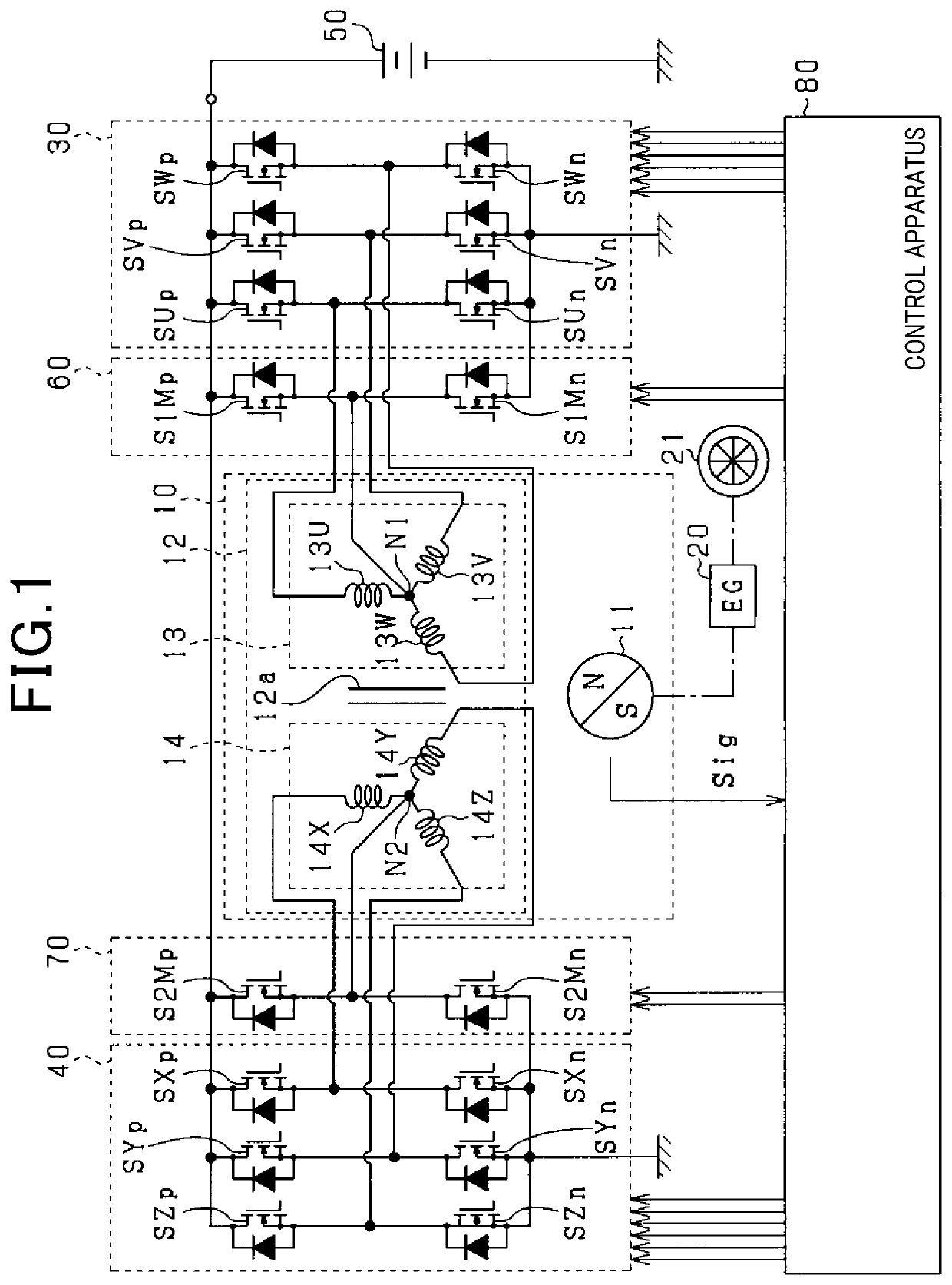
[0104]A second embodiment will be described below with reference to the drawings, focusing of the differences from the above-described first embodiment. According to the present embodiment, as shown in FIG. 10, the first coil 13 and the second coil 14 are wound around the stator core 12a such that a spatial phase difference is present between the first coil 13 and the second coil 14. According to the present embodiment, the above-described spatial phase difference is set to 30 electrical degrees. In FIG. 10, configurations that are identical to the configurations shown in FIG. 1, described above, are given the same reference numbers for convenience.

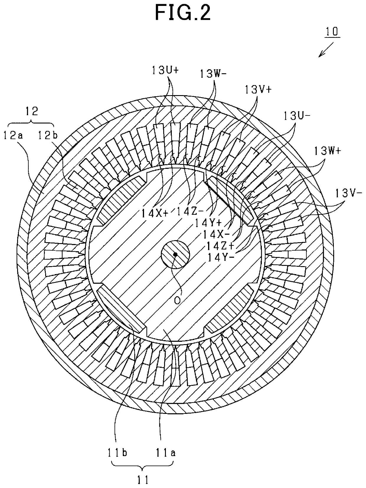
[0105]A configuration of the rotating electric machine 10 according to the present embodiment will be described in detail with reference to FIG. 11. In FIG. 11, configurations that are identical to the configurations shown in FIG. 2, described above, are given the same reference numbers for convenience.

[0106]As shown in FIG. 11, a coil is...

third embodiment

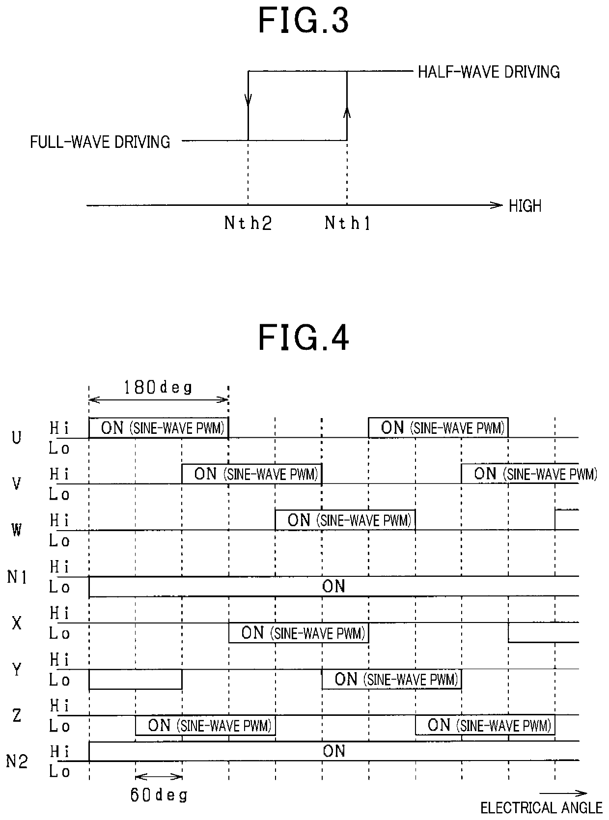
[0108]A third embodiment will be described below with reference to the drawings, focusing of the differences from the above-described first embodiment. According to the present embodiment, as shown in FIG. 13, the peak value of the current flowing to each of the phase coils 13U to 13W and 14X to 14Z configuring the first and second coils 13 and 14 is greater when the half-wave driving process is performed, compared to when the full-wave driving process is performed.

[0109]The energization periods of the first and second coils 13 and 14 when the half-wave driving process is performed are substantially half of those of the first and second coils 13 and 14 when the full-wave driving process is performed. Therefore, a heat generation amount of each of the coils 13 and 14 through which a current flows when the half-wave driving process is performed is substantially half of the heat generation amount of each of the coils 13 and 14 through which a current flows when the full-wave driving pr...

fourth embodiment

[0112]A fourth embodiment will be described below with reference to the drawings, focusing of the differences from the above-described first embodiment. According to the present embodiment, a mode switching process is performed during the half-wave driving process.

[0113]FIG. 15 shows the steps in the mode switching process. For example, the control apparatus 80 repeatedly performs this process at every predetermined period under a condition that the half-wave driving process is being performed.

[0114]In this series of processes, first, at step S10, respective temperatures of the switches SUp to SWn and SXp to SZn configuring the inverters 30 and 40, and the switches S1Mp, S1Mn, S2Mp, and S2Mn configuring the half-bridge circuits 60 and 70 are individually acquired. Here, for example, each temperature may be a detection value from a temperature detecting unit that detects the temperature of each switch.

[0115]At subsequent S11, whether or not any of the temperatures, among the temperat...


PUM


Abstract

A rotating electric machine apparatus includes a rotating electric machine and a full-bridge inverter. The full-bridge inverter includes first high-side switches, first low-side switches, second high-side switches, and second low-side switches. The rotating electric machine apparatus includes: first and second neutral point switches; a full-wave driving unit that performs a full-wave driving process in which switching control of the switches is performed in a state in which the first and second neutral point switches are turned off; a half-wave driving unit that performs a half-wave driving process in which switching control of the first high-side switches and the second low-side switches is performed in a state in which the first and second neutral point switches are turned on, and the first low-side switches and the second high-side switches are turned off; and an executing unit that selects and performs either of the full-wave driving process and the half-wave driving process.

Description

CROSS-REFERENCE TO RELATED APPLICATIONS[0001]The present application is based on Japanese Patent Application No. 2016-140807, filed on Jul. 15, 2016, the descriptions of which are incorporated herein by reference.TECHNICAL FIELD[0002]The present disclosure relates to a rotating electric machine apparatus that is mounted in a vehicle, such as a passenger car or a commercial vehicle, and includes a rotating electric machine and a full-bridge inverter that performs electric power transfer with the rotating electric machine.BACKGROUND ART[0003]In the rotating electric machine that configures this type of apparatus, in cases in which a rotation-speed range over which the rotating electric machine is used as an electric motor is wide, required performance of the rotating electric machine at each of a low-speed range and a high-speed range is required to be obtained. For example, obtaining of the required performance through use of a configuration in which a direct-current to direct-curren...

Claims


Application Information

Patent Timeline
Patent Type & Authority Patents(United States)
IPC IPC(8): H02P6/10H02P6/15H02P27/06H02K3/28H02P25/18H02P25/22
CPCH02K3/28H02P27/06H02P6/153H02P25/18H02P6/10H02P25/22H02P2207/055H02P2209/01H02K11/33
Inventor KIMURA, ASAKATANIGUCHI, MAKOTOKONDO, KEIJI
Owner DENSO CORP
Why Eureka
Try Eureka