
Torque ripple compensation apparatus and method

a compensation apparatus and ripple technology, applied in electrical steering, vehicle sub-unit features, transportation and packaging, etc., can solve the problems of torque ripple or mechanical vibration, time may be required, performance deviation may occur, etc., and achieve the effect of reducing torque rippl

Active Publication Date: 2020-08-27
HYUNDAI MOBIS CO LTD
View PDF0 Cites 1 Cited by
  • Summary
  • Abstract
  • Description
  • Claims
  • Application Information

AI Technical Summary

Benefits of technology

The present invention offers a device and method for reducing torque ripple in an MDPS system of a vehicle when the motor is driven. This can improve steering feel at low speeds.

Problems solved by technology

However, when the MDPS motor is driven, torque ripple or mechanical vibration may occur due to a mechanical structure based on the number of poles in a rotor or the number of slots in a stator.
However, the lookup table-based motor (MDPS motor) control method, in which a parameter extracted through a specific offline experiment is used for motor control, may be easily applied to the MDPS motor control, but has a problem in that a separate test time may be required for the parameter extraction, and a performance deviation may occur due to system distribution.
At this time, when the filter is designed as a low-pass filter to estimate torque ripple which is generated in the form of a trigonometric function, magnitude reduction and phase delay may occur.
Moreover, although the signal correction is performed, it may be difficult to recover an original signal.
Furthermore, parameter estimation through integration requires a long convergence time, and an additional algorithm is required to block divergence of an integration signal.

Method used


Image

  • Torque ripple compensation apparatus and method
  • Torque ripple compensation apparatus and method
  • Torque ripple compensation apparatus and method

Examples


Embodiment Construction

[0037]The invention is described more fully hereinafter with reference to the accompanying drawings, in which embodiments of the invention are shown. This invention may, however, be embodied in many different forms and should not be construed as limited to the embodiments set forth herein. Rather, these embodiments are provided so that this disclosure is thorough, and will fully convey the scope of the invention to those skilled in the art. In the drawings, the size and relative sizes of layers and regions may be exaggerated for clarity. Like reference numerals in the drawings denote like elements.

[0038]As is traditional in the corresponding field, some exemplary embodiments may be illustrated in the drawings in terms of functional blocks, units, and / or modules. Those of ordinary skill in the art will appreciate that these block, units, and / or modules are physically implemented by electronic (or optical) circuits such as logic circuits, discrete components, processors, hard-wired ci...


PUM


Abstract

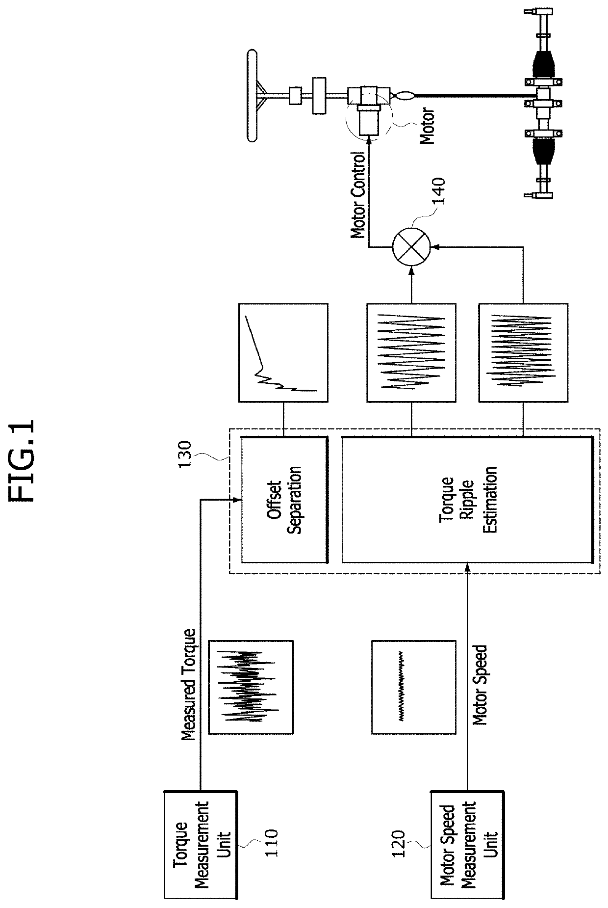
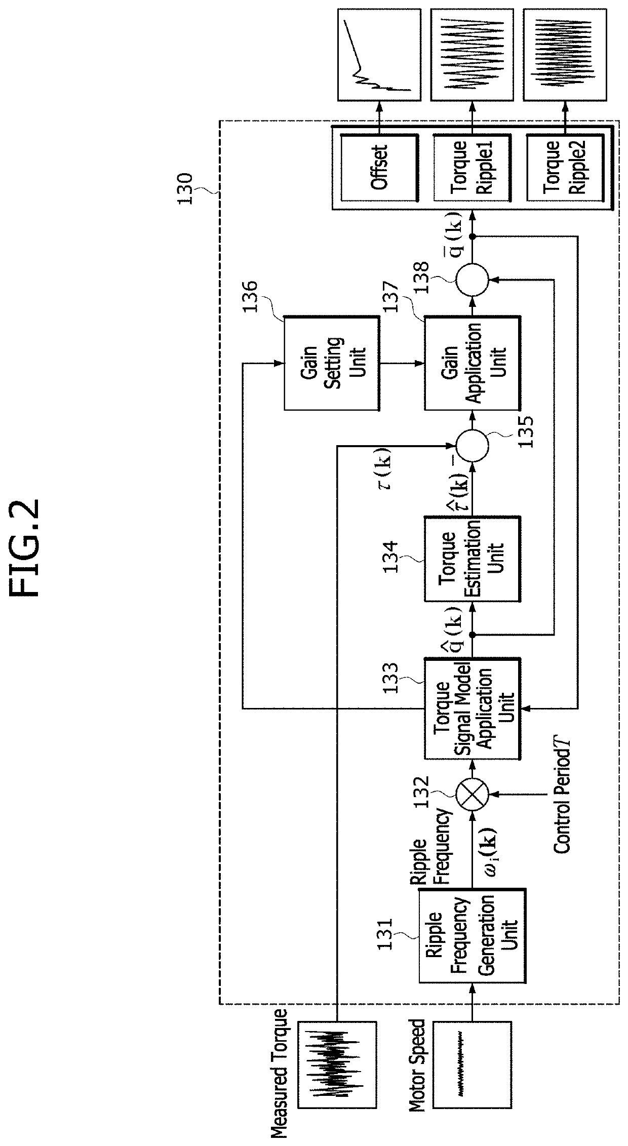
A torque ripple compensation apparatus including a torque measurement unit configured to output torque measured through a torque sensor of an MDPS system; a motor speed measurement unit configured to output motor speed measured through a position sensor of an MDPS motor; a control unit configured to separately output an offset signal and a torque ripple signal based on the motor speed information and the measured torque information; and a torque ripple compensation unit configured to synthesize a plurality of torque ripple signals outputted from the control unit, and output a torque ripple compensation signal as a motor control signal to the MDPS motor, the torque ripple compensation signal being used to compensate for the synthesized torque ripple signal.

Description

CROSS-REFERENCE TO RELATED APPLICATION[0001]The application claims priority from and the benefit of Korean Patent Application No. 10-2019-0020285, filed on Feb. 21, 2019, which is hereby incorporated by reference for all purposes as if fully set forth hereinBACKGROUNDField[0002]Exemplary embodiments of the present invention relate to a torque ripple compensation apparatus and method, and more particularly, to a torque ripple compensation apparatus and method for reducing torque ripple which occurs when a motor of an MDPS (Motor Driven Power Steering) system of a vehicle is driven.Discussion of the Background[0003]An MDPS system of a vehicle provides a part of steering torque which a driver needs to apply to a steering wheel when steering the vehicle, using an auxiliary power source, and thus, enables the driver to easily perform steering.[0004]The MDPS system determines traveling conditions of the vehicle through a column torque sensor configured to measure the driver's column torqu...

Claims


Application Information

Patent Timeline
Patent Type & Authority Applications(United States)
IPC IPC(8): H02P6/10B62D5/04
CPCB62D5/0472H02P6/10B62D5/046B62D5/0463B62D6/10H02P23/0027H02P23/04B60Y2400/307B60Y2400/301
Inventor KIM, IN HYUKKIM, KYU HAJEONG, HYEON HEESEO, JEONG HOON
Owner HYUNDAI MOBIS CO LTD
Learn More