Drawing apparatus and control method for drawing with drawing apparatus
a drawing apparatus and control method technology, applied in the direction of visual representation by plotters, manicure/pedicure, apparel, etc., can solve the problems of low work efficiency, difficult to remove photocurable resin, and thus troublesome process
- Summary
- Abstract
- Description
- Claims
- Application Information
AI Technical Summary
Benefits of technology
Problems solved by technology
Method used
Image
Examples
first embodiment
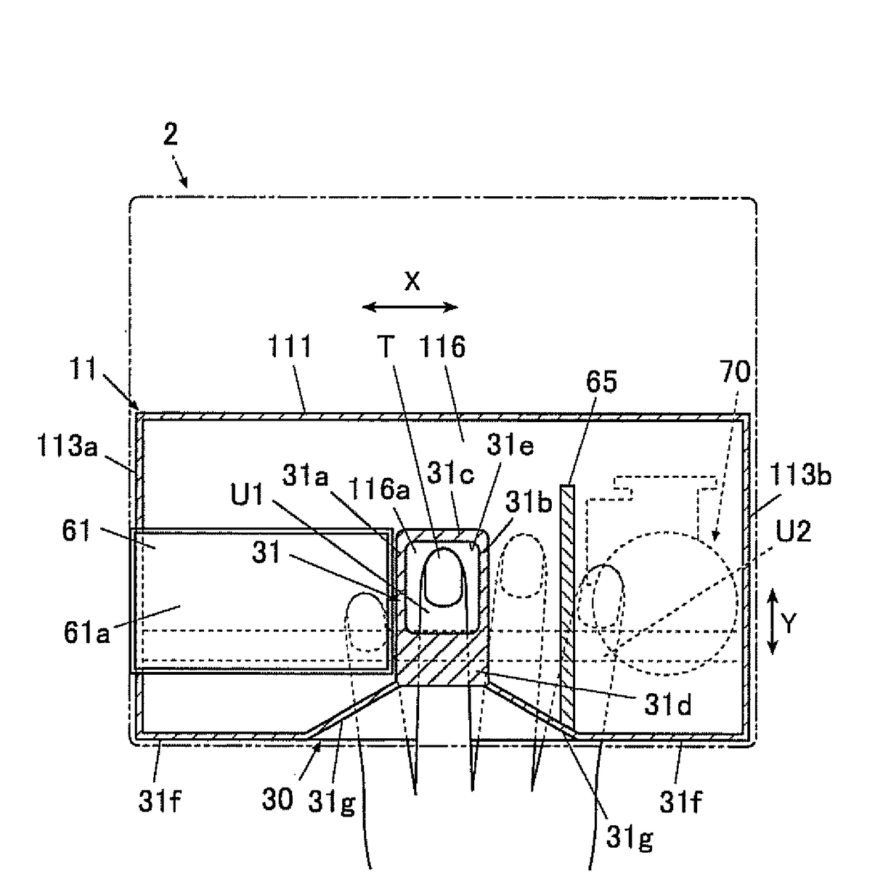
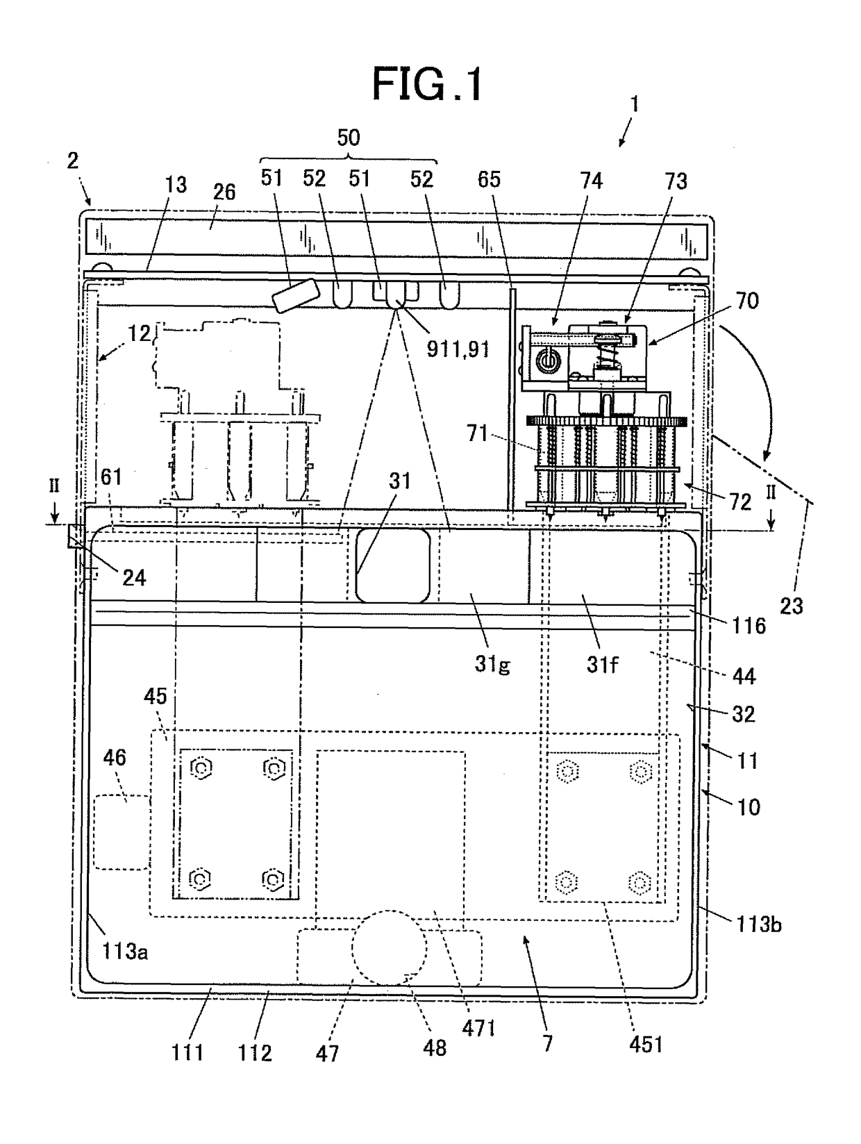
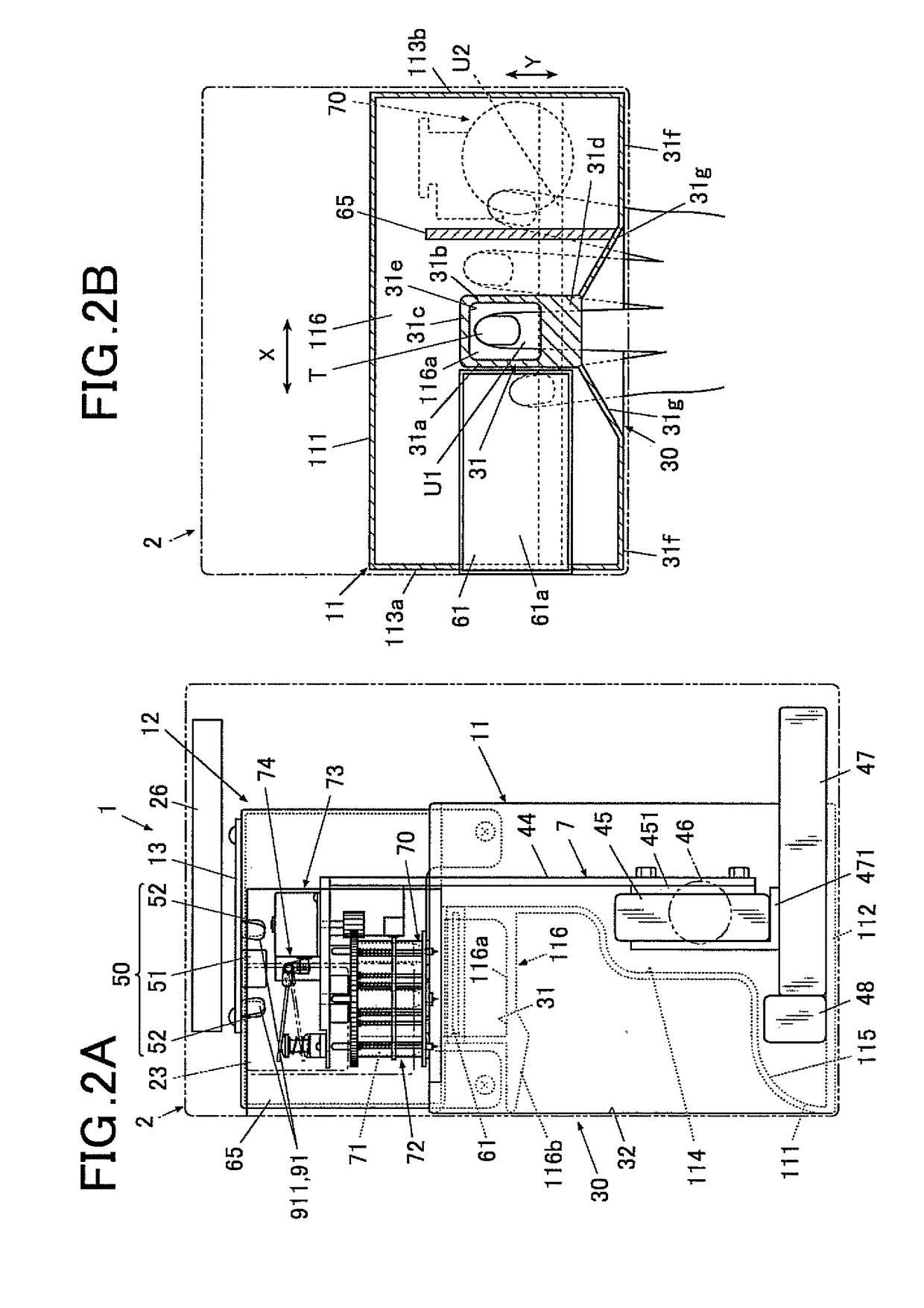
[0047]A drawing apparatus 1 of a first embodiment of the present invention will now be described with reference to FIGS. 1 to 4.
[0048]FIG. 1 is a front view of the drawing apparatus 1 showing the internal configuration of the drawing apparatus 1.
[0049]FIG. 2A is a side view of the drawing apparatus 1 of FIG. 1, a part of which is shown in section to describe the internal configuration.
[0050]FIG. 2B is a sectional view along the line II-II of FIG. 1.
[0051]As shown in FIGS. 1, 2A and 2B, the drawing apparatus 1 of this embodiment is a plotter drawing apparatus including a drawing head 70 with pens 71 to perform drawing on the nails T of printing fingers U1.
[0052]The drawing apparatus 1 includes a case body (casing) 2 and an apparatus body 10 contained in the case body 2.
[0053]A cover 23 for pen replacement is disposed at one end of the upper part of the lateral face of the case body 2. The cover 23 can be opened and closed so that a pen (drawing tool) 71 of a drawing unit 7, described...
second embodiment
[0252]A drawing apparatus and a control method for drawing with a drawing apparatus of a second embodiment of the present invention will now be described with reference to FIGS. 5A to 6C.
[0253]The second embodiment is different from the first embodiment mainly in the position of a light irradiation mechanism, and the following description mainly focuses on the features different from those of the first embodiment.
[0254]FIG. 5A is a front view of a drawing apparatus 1 showing the internal configuration.
[0255]FIG. 5B is a side view of the drawing apparatus 1 of FIG. 5A, a part of which is shown in section to describe the internal configuration of the drawing apparatus 1.
[0256]As shown in FIGS. 5A and 5B, the drawing apparatus 1 of the second embodiment is a plotter drawing apparatus including a drawing head 42 having pens 41 to perform drawing on nails T of printing fingers U1, as in the first embodiment.
[0257]In this embodiment, the drawing head 42 includes three pen carriages 43 eac...
third embodiment
[0320]A drawing apparatus of a third embodiment of the present invention will now be described with reference to FIGS. 7A to 8B.
[0321]The third embodiment is different from the first and second embodiments mainly in the position of a light irradiation mechanism, and the following description mainly focuses on the features different from those of the first and second embodiments.
[0322]FIG. 7A is a front view of a drawing apparatus 1 showing the internal configuration.
[0323]FIG. 7B is a side view of the drawing apparatus 1 of FIG. 7A, a part of which is shown in section to describe the internal configuration of the drawing apparatus 1.
[0324]As shown in FIGS. 7A and 7B, the drawing apparatus 1 of the third embodiment is a plotter drawing apparatus including a drawing head 70 having a rotary pen carriage 72 holding pens 71 to perform drawing on nails T of printing fingers U1, as in the first embodiment.
[0325]As shown in FIGS. 7A and 7B, the drawing head 70 in this embodiment holds a lig...
PUM
 Abstract
Description
Claims
Application Information
 - R&D
- Intellectual Property
- Life Sciences
- Materials
- Tech Scout
- Unparalleled Data Quality
- Higher Quality Content
- 60% Fewer Hallucinations
Browse by: Latest US Patents, China's latest patents, Technical Efficacy Thesaurus, Application Domain, Technology Topic, Popular Technical Reports.
© 2025 PatSnap. All rights reserved.Legal|Privacy policy|Modern Slavery Act Transparency Statement|Sitemap|About US| Contact US: help@patsnap.com


