
Card

a greeting card and card body technology, applied in the field of articles, can solve the problems of not being able to meet the needs of use, being difficult to display etc., and achieve the effect of not being able to meet the needs of use, and being difficult to er

Active Publication Date: 2017-05-02
VINECOMBE BARBARA JEAN
View PDF18 Cites 0 Cited by
  • Summary
  • Abstract
  • Description
  • Claims
  • Application Information

AI Technical Summary

Benefits of technology

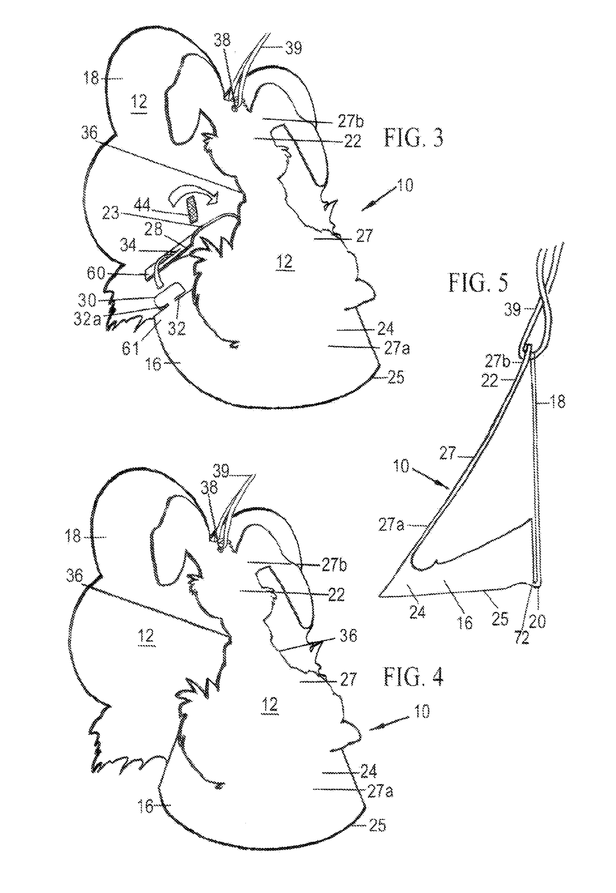
[0025]Preferably, the central portion comprises the first edge and the slot, and therebetween is located a heel section. When the central portion and versatile portion are in the three dimensional form, and resting on a support surface, the heel section provides balance and stability for the three dimensional form. Dimensions of the heel section can be varied to suit balance and stability requirements of alternative arrangements, with the first edge conforming accordingly.
[0043]According to a third aspect of the invention, as illustrated in FIG. 6, the central portion either prior to or when erected into the three-dimensional form, can be adapted to receive a weight to enhance the stability of the three-dimensional form when resting on a support surface. The weight can be attached to the rear side of the front face of the central portion when flat, as or when the central portion is erected in the three-dimensional form.
[0045]In an alternative arrangement there can be numerous versatile portions representing candles connected at the first edge of the central portion. The sender can remove the number of candles exceeding the required number for the birthday occasion by cutting same from the first edge at the fold without detracting from the card.

Problems solved by technology

The booklet style greeting card generally is often difficult to display and when the greeting card is displayed, only the front cover or the inside cover or page are displayed and a slight breeze will topple them off the furniture.
While some such proposals may be effective in creating interest and allowing display in the three-dimensional form, they can be rather complicated to erect and / or not sufficiently stable when in the erected condition for display purposes.

Method used


Image

  • Card
  • Card
  • Card

Examples


first embodiment

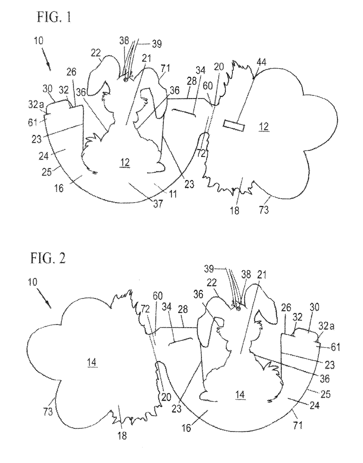
[0071]Referring to the FIGS. 1 to 6 of the drawings, there is shown an article configured as a greeting card 10 according to the The greeting card 10 is illustrated in FIGS. 1 and 2 in two-dimensional form, comprising a sheet 11 having a front side 12 and a rear side 14. The sheet 11 comprises a first portion defined as the central portion 16, a second portion defined as a versatile portion 18 and a fold line defined as fold 20. The versatile portion 18 is attached to the central portion 16 through the fold 20. The central portion 16 and the versatile portion 18 are connected via the fold 20. The central portion 16 and the versatile portion 18 are formed from a single piece of material. The greeting card 10 may be manufactured from a paper stock of suitable thickness. In an alternative embodiment the greeting card may be manufactured from a wide variety of materials, such as, but not limited to, paper, cardboard, plastics, minerals and parchment paper. Typically, the sheet stock is...

third embodiment

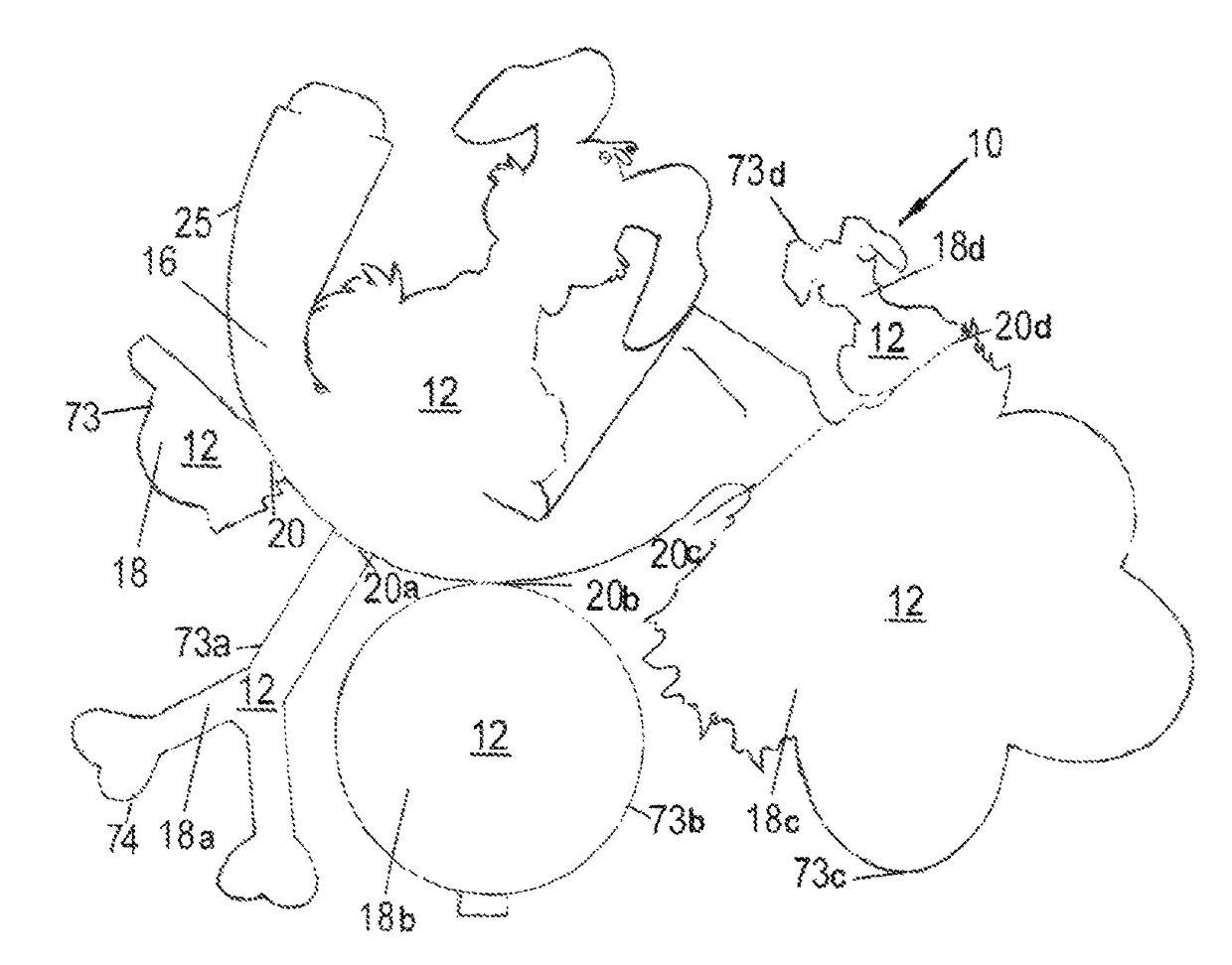
[0102]FIG. 7 According to the invention as illustrated in FIG. 7, there is an article comprising a sheet defining a central portion 16, and a versatile portion 18 and a further four versatile portions 18a, 18b, 18c and 18d, connected together. The central portion 16 being adapted for erection into a three-dimensional form, the versatile portion 18 being adapted to the role of a foreground to the central portion 16 in the three-dimensional form, a further versatile portion 18a being adapted to the role of an internal portion 74 to the central portion 16 in the three-dimensional form, a further versatile portion 18b being adapted to the role of a base to the central portion 16 in the three-dimensional form, and a further versatile portion 18c being adapted to the role of a background to the central portion 16 in the three-dimensional form, and a further versatile portion 18d being adapted to the role of a foreground to the versatile portion to 18c in the role of a background to the ce...

fourth embodiment

[0104]FIG. 9 According to the invention as illustrated in FIG. 9, there is an article comprising a sheet defining a central portion 16, and a versatile portion 18 and a further versatile portion 18a connected together, the central portion 16 being adapted for erection into a three-dimensional form to provide a central portion, and the versatile portion 18 adapted to provide a base 54 to the central portion 16 and the further versatile portion 18a being adapted to provide a foreground to the three-dimensional form. The heel section 72 is also clearly illustrated.

[0105]FIGS. 10, 11 & 12 According to the fourth embodiment of the invention as illustrated in FIG. 9, the central portion 16 consists of a heel section 72. When the erected three dimensional form 16 is sitting on a surface, the heel section 72 provides an even distribution of weight to the first edge 25 of the central portion 16 and balance and stability for the three dimensional form 16. The dimensions of the heel 72 are adj...


PUM

PropertyMeasurementUnit
angleaaaaaaaaaa
weightaaaaaaaaaa
period of timeaaaaaaaaaa

Abstract

An article such as a greeting card (10) comprising a sheet (11) defining at least one central portion (16) and at least one versatile portion (18) connected together via at least one fold (20). The central portion (16) has two opposing edges (26, 28) adapted to be drawn together to create a three-dimensional form. The fold (20) is located at a junction of the central portion (16) and versatile portion (18). These portions (16, 18) are foldably connected together whereby the versatile portion (18) can be folded and adapted for location adjacent to or at an angle to the three-dimensional form, and may be secured at that location. The greeting card (10) may further comprise numerous engagement means (30, 32), apertures (38) and cords (39). The greeting card (10) can be delivered in a collapsed condition and can be readily assembled into a three-dimensional form revealing the ingenuity of the card.

Description

PRIORITY[0001]This application claims priority of U.S. patent application Ser. No. 11 / 654,125 filed Jan. 16, 2007.FIELD OF THE INVENTION[0002]The present invention relates to an article that can transform from a collapsed condition, which is generally flat, into an erected condition that has a three-dimensional form, and can transform back to its collapsed condition.[0003]The article may be used for any appropriate purpose such as, for example, a greeting card to convey a greeting message or other information; a decoration; a gift; a souvenir; an ornament; a puzzle; entertainment; a table name card; an educational tool; promotional tool or display device for advertising or conveying other information.BACKGROUND ART[0004]The discussion of the background art is included exclusively for the purpose of providing a context for the present invention. It should be appreciated that the discussion is not an acknowledgement or admission that any of the material referred to was common general ...

Claims


Application Information

Patent Timeline
Patent Type & Authority Patents(United States)
IPC IPC(8): G09F1/06B42D15/04B32B7/04G09F1/08G09F1/02
CPCG09F1/06B32B7/04B42D15/042G09F1/08
Inventor VINECOMBE, BARBARA JEAN
Owner VINECOMBE BARBARA JEAN
Learn More