
Eye marker device

a marker and eye technology, applied in the field of eye markers, can solve the problems of inability to use markers outside of the operating room, inability to accurately place marks, and inability to transfer ink to the eye surface of all markers currently used,

Active Publication Date: 2016-03-15
MINDSKID LABS
View PDF9 Cites 3 Cited by
  • Summary
  • Abstract
  • Description
  • Claims
  • Application Information

AI Technical Summary

Benefits of technology

The present invention provides an eye marker device with improved balance, stability, and rotational alignment. The device includes a handle with a weight or a bearing positioned inside to ensure stability and alignment. The device also includes a post with marking head, marking tip, and support means for stability. The technical effects of the invention involve improved usability and accuracy of the eye marker device.

Problems solved by technology

All markers currently used suffer from issues of inadequate ink transfer to the eye surface principally due to the fact that only a thin layer of ink is being transferred to an ocular surface and that surface is wet from the ocular tear film.
The error in marking an eye with the patient lying down can be in the 20 degree range which is very clinically significant.
Because metal markers retain only a thin film of ink that is blinked off within a few minutes, they cannot be used for marking outside of the operating room.
Clearly the above system to mark the eye for the treatment of astigmatism is complex and creates limitations as to the accuracy of the marks placed, how the procedure is performed and how the patient flow is achieved.

Method used


Image

  • Eye marker device
  • Eye marker device
  • Eye marker device

Examples


Embodiment Construction

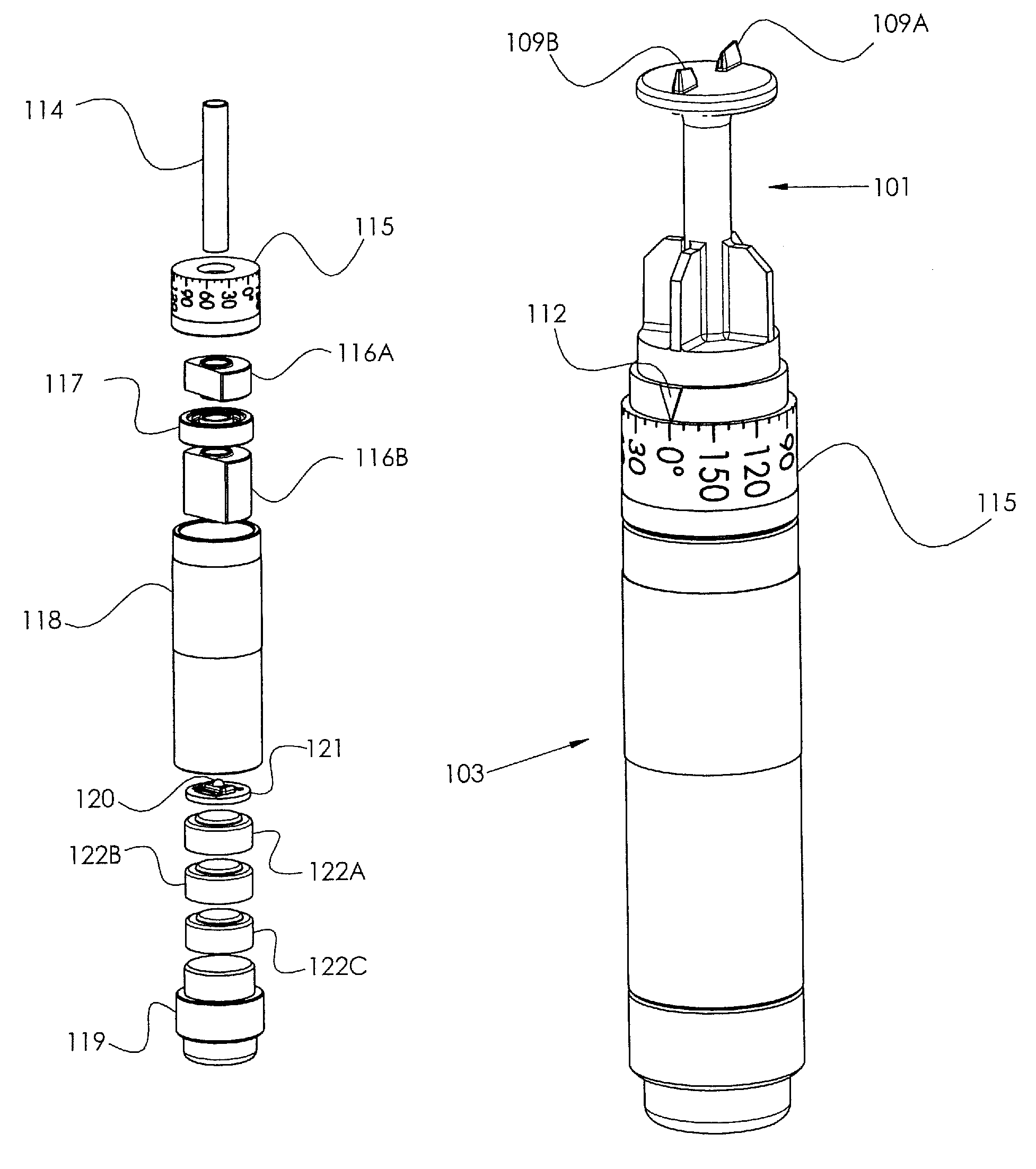
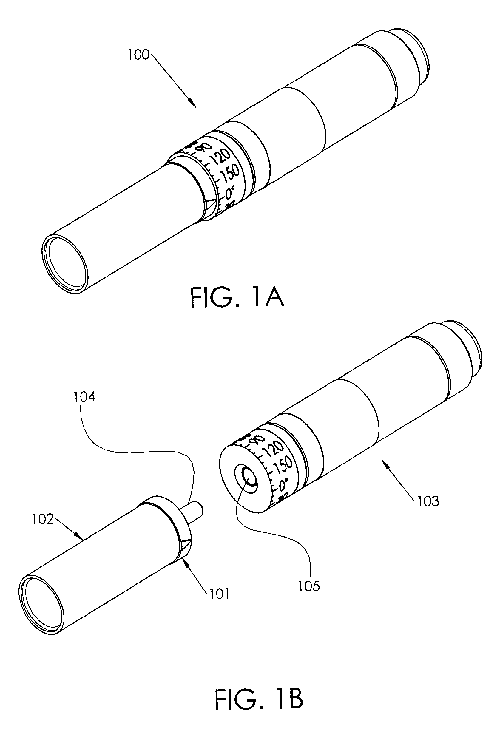
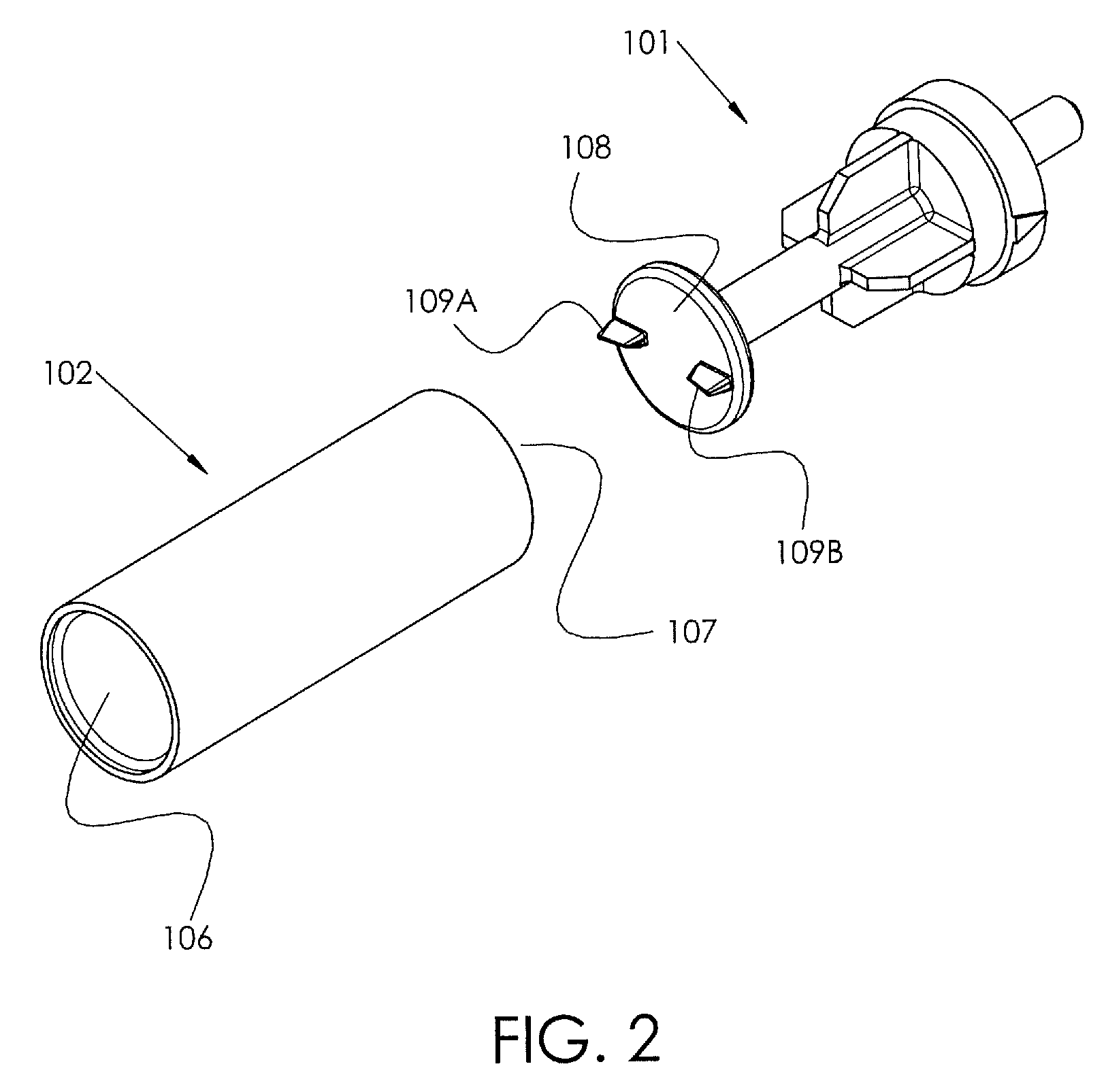
[0051]Referring now specifically to the drawings, an eye marker device is illustrated in FIGS. 1A and 1B and is shown generally at reference numeral 100. The device 100 comprises a marking means 101, and a sleeve 102 that is assembled to a handle 103. One embodiment of the marking means 101, as shown in FIGS. 2 and 3, contains a post 104 with a first end and a second end. A marking head 108 is disposed on the first end of the marking means 101 and contains a marking end and a posterior end. The marking head 108 is generally cylindrical in shape, but may be alternatively shaped, by way of example only, and not limited to, generally square, generally rectangular, generally trapezoidal, or generally oval. The first end of the post 104 is engaged to the posterior end of the marking head 108 and extends distally from the posterior end of the marking head 108.

[0052]The marking end of the marking head 108 comprises at least one marking tip (109A, 109B). As illustrated in the exemplary embo...


PUM


Abstract

The present invention provides methods and systems for an eye marker device that includes a handle having an interior cavity, a marking means coupled to the handle, and a rotational scale for providing a visual representation of the angle of the marking means relative to a predetermined origination point.

Description

CROSS REFERENCE TO RELATED PATENT APPLICATION[0001]The current application claims the benefit of the earlier priority filing date of the provisional application, Ser. No. 61 / 466,506, that was filed on Mar. 23, 2011.FIELD OF THE INVENTION[0002]The present invention relates generally to an eye marker device and more generally relates to an eye marker device that is internally weighted for providing a mark or indicator on the surface of the eye.BACKGROUND OF THE INVENTION[0003]The current invention addresses the problem of long lasting accurate ink marks applied to the ocular surface as needed for the correction of astigmatism.[0004]In the field of refractive surgery there exists a need to place ink marks on the eye in order to orient the treatment of astigmatism. Astigmatism is a condition where the shape of the cornea bends light to more than one focal point causing a blurred image upon the retina. Astigmatism caused by the cornea is described as corneal astigmatism or corneal cylind...

Claims


Application Information

Patent Timeline
Patent Type & Authority Patents(United States)
IPC IPC(8): A61B17/00A61F9/013
CPCA61F9/0136A61B90/30A61B2090/309
Inventor BROWN, ALAN, WESLEY
Owner MINDSKID LABS
Learn More