Plug connector with capability of dual mating orientation

a technology of plug connector and connector, applied in the direction of coupling contact member, coupling device connection, two-part coupling device, etc., can solve the problem of unfavorable use of conventional usb connector, and achieve the effect of enhancing convenience in us

Active Publication Date: 2017-05-02
ADVANCED CONNECTEK INC
View PDF12 Cites 5 Cited by
  • Summary
  • Abstract
  • Description
  • Claims
  • Application Information

AI Technical Summary

Benefits of technology

[0026]In summary, the main body, the first spring arm, the first end portion, the second spring arm and the second end portion of the plug contact of the present invention are an integrally-formed fork structure. Accordingly, when the port contact is mounted with the housing base, the first end portion and the second end portion of the plug contact respectively stretch out of the tongue structure of the housing base and face to each other, such that the plug connector of the present invention is capable of dually mating with an external connector for enhancing convenience in use.

Problems solved by technology

In such a way, the conventional USB connector is not convenient in use.

Method used


Image

  • Plug connector with capability of dual mating orientation
  • Plug connector with capability of dual mating orientation
  • Plug connector with capability of dual mating orientation

Examples


first embodiment

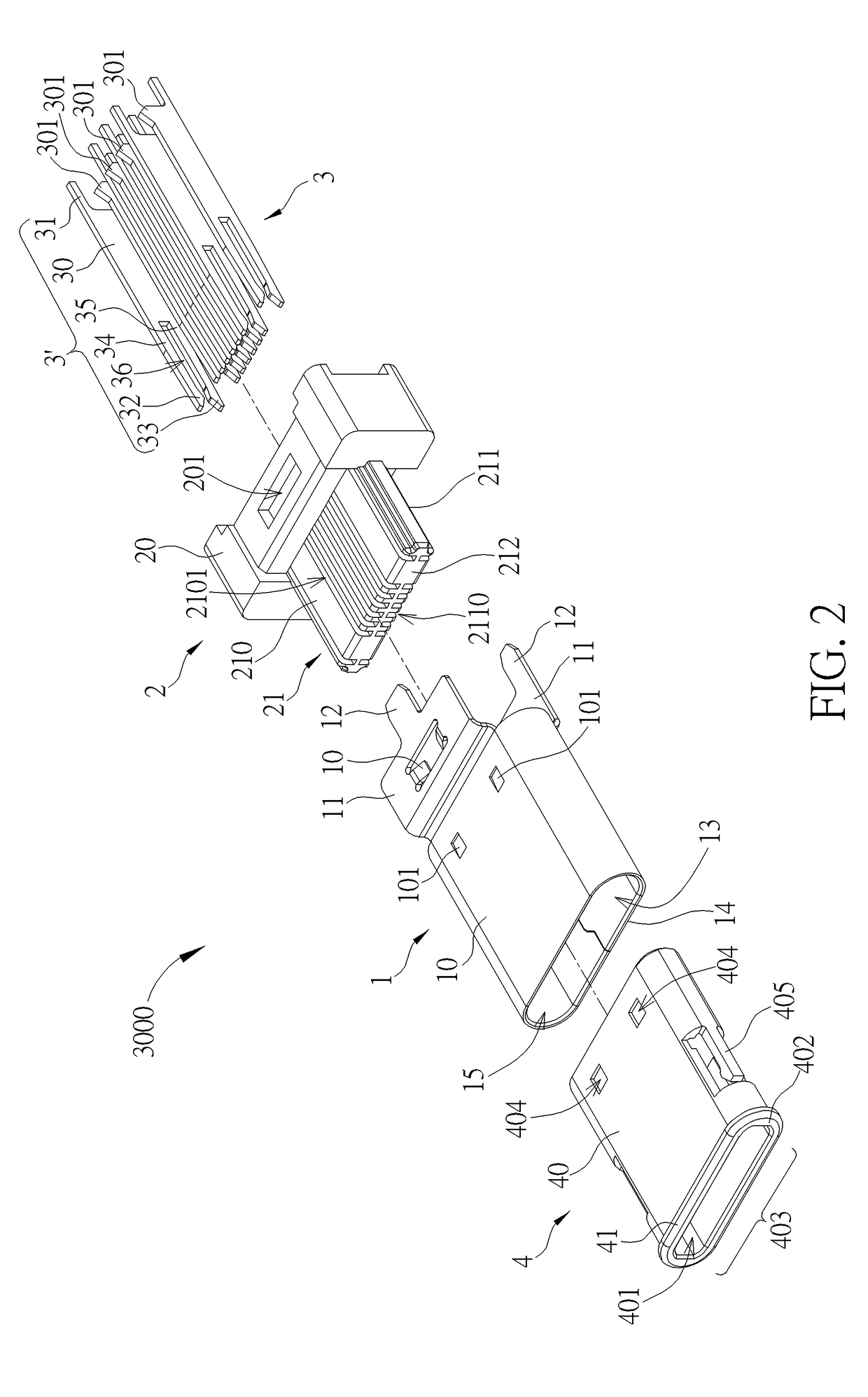
[0051]Please refer to FIG. 4 and FIG. 6. FIG. 6 is an exploded diagram of the plug connector 3000 in the non-mated status and at another view according to the present invention. As shown in FIG. 4 and FIG. 6, a partition structure 213 is defined by a bottom surface S1 of the first slot 2101 and a bottom surface S2 of the second slot 2110 of the tongue structure 21 as well as a lateral wall S3 of the assembling slot 202 of the main base 20. A clamping slot 36 is defined between the first spring arm 34 and the second spring arm 35. After the plug contacts 3′ is installed with the housing base 2, the clamping slot 36 clamps the partition structure 213. In such a manner, the partition structure 213 provides the first spring arm 34 and the second spring arm 35 of the plug contacts 3′ with a stop, so as to stop the first end portion 32 and the second end portion 33 from over deformation during mating, which enhances life of plug connector 3000.

[0052]As shown in FIG. 2, FIG. 3 and FIG. 5, ...

second embodiment

[0055]Please refer to FIG. 8. FIG. 8 is an exploded diagram of a plug connector 3000′ according to the present invention. As shown in FIG. 8, the main difference between the plug connector 3000′ and the aforesaid plug connector 3000 is that each foot portion 31′ of a plug contact 3′ of the plug connector 3000′ includes a first pin 310 and a second pin 311, and a pin slot 312 is defined between the first pin 310 and the second pin 311. When the plug connector 3000′ is disposed on an edge of the circuit board, the pin slot 312 is for clamping the edge of the circuit board, so as to fix the plug connector 3000′ and the circuit board. In addition, a base slot 203 is formed on a main base 20′ of a housing base 2′ of the plug connector 3000′ and is located corresponding to the pin slot 312. The base slot 203 and the pin slot 312 cooperatively clamp the edge of the circuit board, such that the plug connector 3000′ is able to be fixed on the circuit board more stably.

[0056]Please refer to F...


PUM


Abstract

A plug connector includes a plug shell, a housing base and a plug contact. The housing base is combined with the plug shell and includes a main base and a tongue structure. The tongue structure extends from the main base and has a first face and a second face opposite to the first face. The plug contact includes a main body, a foot portion, a first end portion and a second end portion. The main body is mounted in the main base. The foot portion extends from the main body and stretches out of the main base. The first end portion is resiliently connected to the main body and protrudes out of the tongue structure via the first face. The second end portion corresponding to the first end portion is resiliently connected to the main body and protrudes out of the tongue structure via the second face.

Description

BACKGROUND OF THE INVENTION[0001]1. Field of the Invention[0002]The present invention relates to a connector, and more particularly, to a plug connector adapted to a Universal Serial Bus interface and with capability of dual mating orientation.[0003]2. Description of the Prior Art[0004]With development of computer and peripheral equipment industry, a Universal Serial Bus (USB) interface has become one of important interfaces for communication and data transmission between a computer and peripheral equipment. A USB connector usually has a specified orientation when mating, i.e., a tongue of a USB male connector and a USB female connector are staggered, such that the tongue of the USB male connector is able to be inserted into a socketing space surrounded by a metal shell of the USB female connector. It ensures that the USB male connector is inserted into the female connector properly and that terminals of the USB male connector are electrically connected to terminals of the USB femal...

Claims


Application Information

Patent Timeline
Patent Type & Authority Patents(United States)
IPC IPC(8): H01R24/00H01R24/60H01R13/642H01R107/00
CPCH01R13/642H01R24/60H01R2107/00H01R13/05H01R13/502
Inventor CHEN, CHING-TIENDUAN, SHU-LINWAN, WEIXU, FU-YI
Owner ADVANCED CONNECTEK INC
Why Eureka
Try Eureka