
Safety shredder with bin-full device and time delay

a safe and reliable technology, applied in the field of paper shredders, can solve the problems of difficult to continue paper shredding, damage to paper-full detection devices, unstable electronic paper-full detection devices,

Active Publication Date: 2017-05-09
AURORA OFFICE EQUIP
View PDF32 Cites 7 Cited by
  • Summary
  • Abstract
  • Description
  • Claims
  • Application Information

AI Technical Summary

Benefits of technology

[0010]The second restriction member is a limit bar and is set to be parallel to the first restriction member. The touching device can be a poke rod which is installed on the lower housing of the shredder through axially connecting to a branch component that is pivotally connected to the lower housing of the shredder. The inner side of the shredder waste bin is set with a support that can prop up one end of the poke rod when a drawing-type waste bin of the shredder is pushed in, thus enabling it rotate to contact the contact point of the contact switch. The support can be set with a first restriction member that can prop up one end of the poke rod when the drawing-type waste bin of the shredder is pushed in, thus enabling the support rotate to contact the contact point of the contact switch. The support can be equipped with a second restriction member that is used for restricting the moving distance of the poke rod upon being pushed by the touching element of the pressing plate.
[0013]Yet another embodiment of the present invention provides a time-delay mechanism of shredder integrated with a safety switch of power-off function, responsive to the lifting of the shredder head, having a time-delay switch body, in which the time-delay switch body can be provided with a forced rod. The paper waste bin of the shredder is provided with a support rib corresponding to the forced rod. One end of the forced rod is connected to the time-delay switch body through pivoting connection and the other end is connected to the support rib by means of touch. When the shredder head is put into the waste bin, under the driving of the support rib, the forced rod can drive the time-delay switch body to rotate and leave it in the contact state with the paper entrance.

Problems solved by technology

A fully-filled waste bin makes it difficult to continue the paper shredding, and high-piled scraps easily damage the paper-full detection device.
The electronic paper-full detection device is fairly expensive and unstable, while the currently existing mechanical paper-full detection device has the shortcomings of being complicated in structure and inflexible to use.
In view of energy saving and safety, the shredder is usually provided with a time-delay switch and a safety switch of power-off function when the shredder head is lifted, but normally these two switches are installed separately, thus increasing the number of parts for the shredder and the manufacturing cost.

Method used


Image

  • Safety shredder with bin-full device and time delay
  • Safety shredder with bin-full device and time delay
  • Safety shredder with bin-full device and time delay

Examples


example embodiment 1

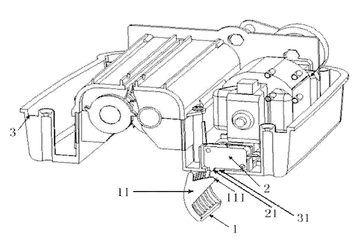
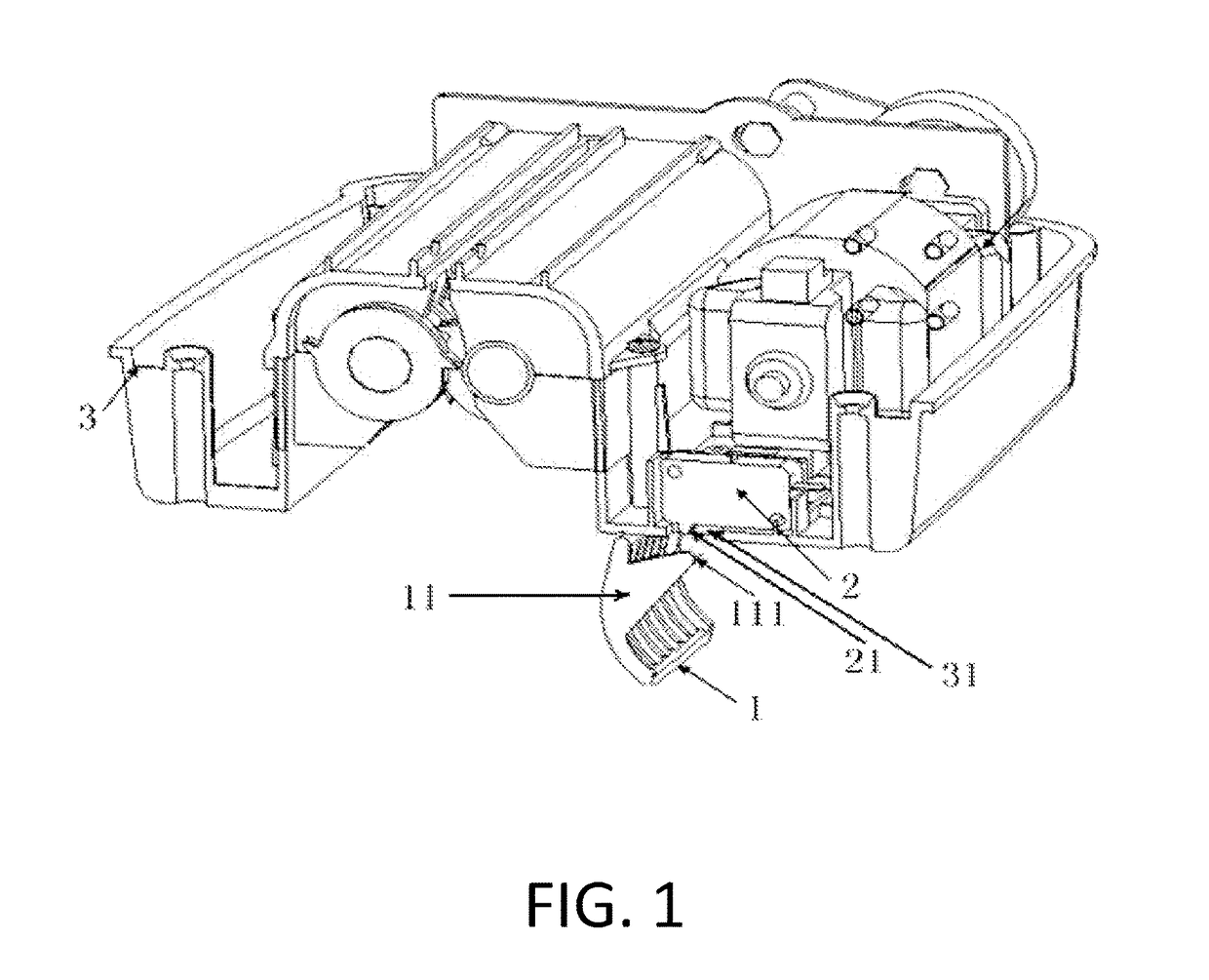
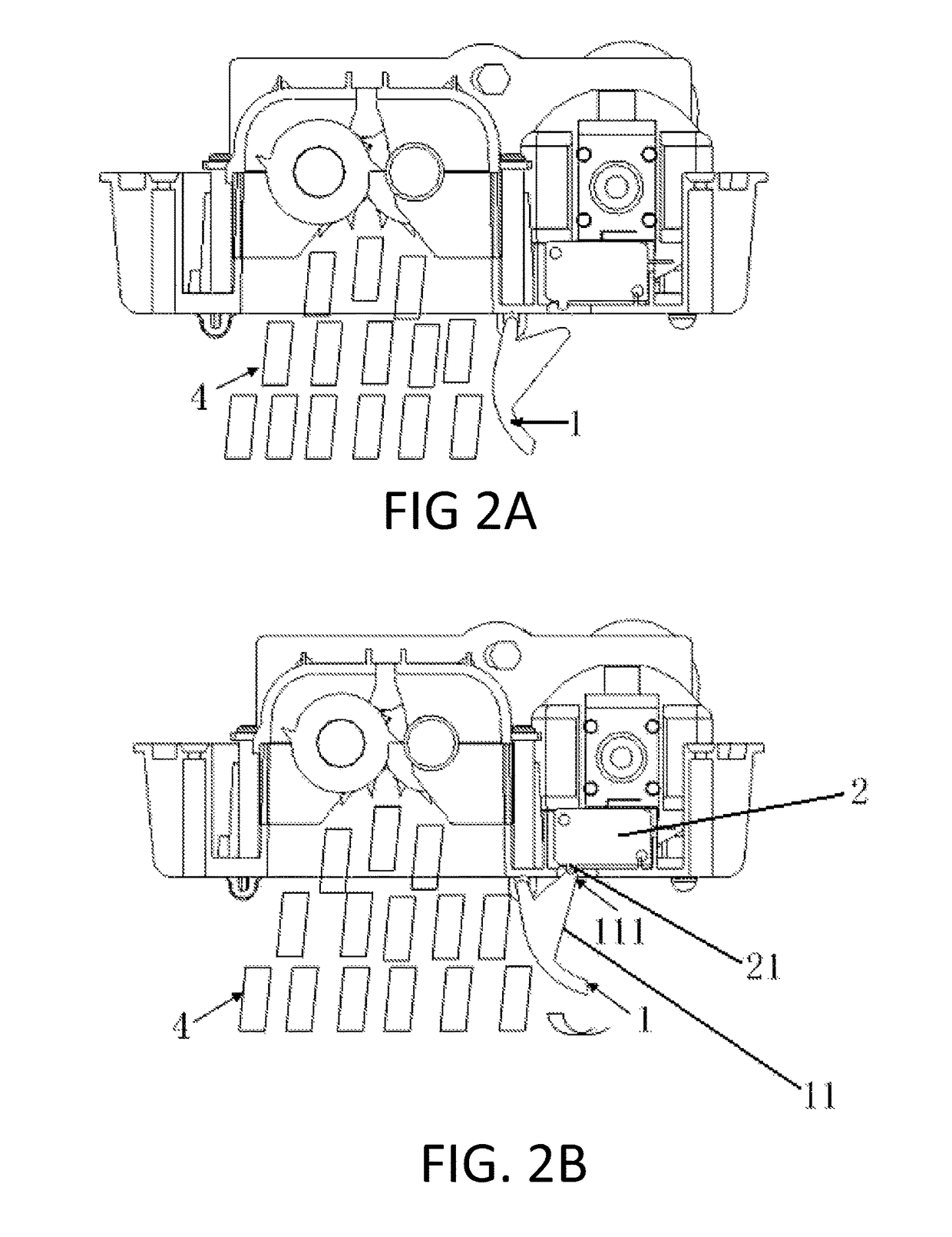
[0037]In FIG. 1, the mechanical bin-full device of a paper shredder in this embodiment includes a pressing plate 1, a contact switch 2, and a touching part, which can be touching plate 11. Pressing plate 1 can be installed at the outside of the mechanical parts of the shredder under the lower housing 3 of the shredder, and parallel to the cutter shaft of the mechanical parts of the shredder, one end of which is connected to the lower housing 3 of the shredder through pivoting connection, such as rotation shaft, and the other end can freely swing. In other embodiments of the present invention, the pressing plate may be not parallel to the cutter shaft of the shredder. It can present a smaller, more acute, angle with the cutter shaft of the shredder.

[0038]A contact switch 2, fixed on the lower housing 3 of the shredder, and a contact point 21 is provided on one side of the contact switch 2 which is near the lower housing 3 of the shredder; the contact switch 2 is a micro-switch in thi...

example embodiment 2

[0040]The difference of this embodiment from example Embodiment 1 is that the touching part installed on the pressing plate is a touching rod.

example embodiment 3

[0041]As shown in FIG. 3-6, the shredder in this embodiment includes the mechanical parts of the shredder 101, the lower housing 102 of the shredder, as well as the shredder mechanical bin-full device. FIG. 5 and FIG. 6 are cross-sectional drawings of the application processes of the paper-full detection functions by the shredder mechanical bin-full device. FIG. 7 and FIG. 8 are drawings of the structure by another mechanical bin-full device of shredder and on the application processes of the paper-full detection functions by another implementation of a shredder mechanical bin-full device.

[0042]The mechanical bin-full device of this embodiment chiefly consists of a contact switch, a touching device, and a pushing device. The contact switch, which is a safety switch 103 in this embodiment, may be fixedly installed on the lower housing of the shredder 102. The safety switch 103 is equipped with a contact point 131 that is to be contacted when the shredder head is put into the waste bi...


PUM


Abstract

A mechanical bin-full device for a paper shredder with a pressing plate, a contact switch, and a touching part. The pressing plate is installed at an outside portion of the shredder mechanical parts under the lower housing. One end of the pressing plate is pivots on the lower housing and the other end is free. The contact switch is fixed on the lower housing and a contact point is provided on the contact switch. The touching part is provided on the pressing plate, away from the mechanical parts. The lower housing has a through-hole under the contact point of the contact switch enabling the touching part to contact the contact point. The waste paper drives the pressing plate to turn around the joint between it and the lower housing, making the touching part touch the contact point of the contact switch and making the shredder power off.

Description

BACKGROUND[0001]1. Field of the Invention[0002]The present invention relates to paper shredder, in particular, to a mechanical bin-full device of paper shredder.[0003]2. Background Art[0004]The shredder presently is a machine that is commonly used to destroy confidential documents. Generally, the shredder comprises a paper-shredding device and a waste bin. A fully-filled waste bin makes it difficult to continue the paper shredding, and high-piled scraps easily damage the paper-full detection device. The existing paper-full detection devices chiefly comprise two types: the mechanical one and the electronic one. The electronic paper-full detection device is fairly expensive and unstable, while the currently existing mechanical paper-full detection device has the shortcomings of being complicated in structure and inflexible to use.[0005]In view of energy saving and safety, the shredder is usually provided with a time-delay switch and a safety switch of power-off function when the shred...

Claims


Application Information

Patent Timeline
Patent Type & Authority Patents(United States)
IPC IPC(8): B02C23/04B02C18/00B02C25/00
CPCB02C23/04B02C18/0007B02C25/00B02C2018/0023
Inventor LIU, WEISUN, YINGPENGTSO, YUNG KANG
Owner AURORA OFFICE EQUIP
Learn More