Movable handle

a technology of handle and handle, which is applied in the field of handles, can solve the problems of loosened screws or nuts, increased manufacturing costs, and less competitive in the market,

Active Publication Date: 2017-08-24
FIVETECH TECH INC
View PDF3 Cites 4 Cited by
  • Summary
  • Abstract
  • Description
  • Claims
  • Application Information

AI Technical Summary

Benefits of technology

[0017]In the above embodiment, the elastic element can exert a spring force on the movable member and therefore produces a frictional resistance between the movable member and the seat or the elastic element when the movable member is moved.
[0047]In the above embodiment, the movable handle further includes a limiting element, which is fixed to the seat to extend through the movable member or the corresponding movable member for limiting a moving distance allowed for the movable member or the corresponding movable member.

Problems solved by technology

In the case of a conventional movable handle assembling structure that involves a relatively complicated structure, it requires increased manufacturing cost and is therefore less competitive in the market.
When the handle is operated and turned, it tends to bring the screws or the nuts to rotate along with it to finally cause loosened screws or nuts.

Method used


Image

  • Movable handle
  • Movable handle
  • Movable handle

Examples


Embodiment Construction

[0096]The present invention will now be described with some preferred embodiments thereof and by referring to the accompanying drawings. For the purpose of easy to understand, elements that are the same in the preferred embodiments are denoted by the same reference numerals.

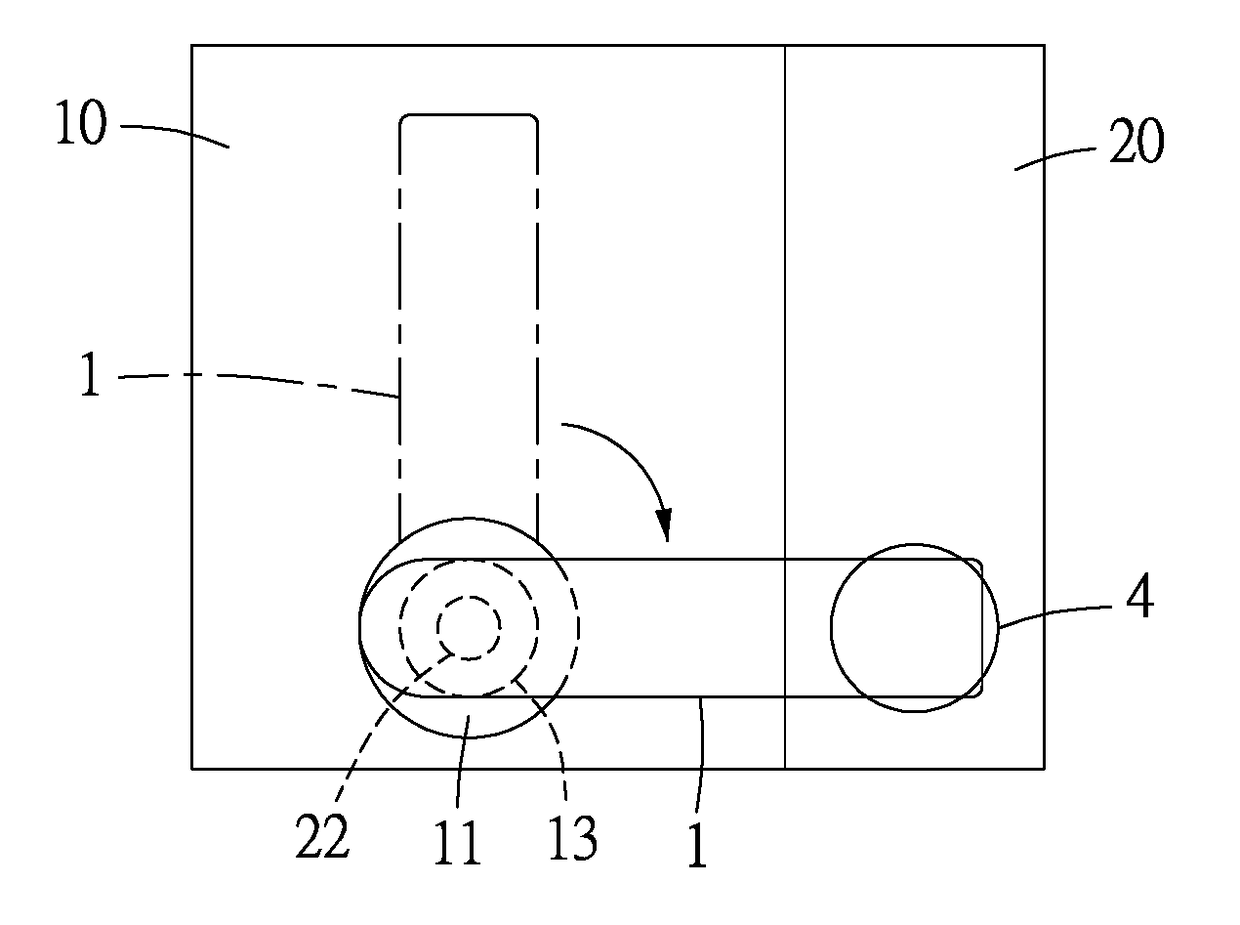
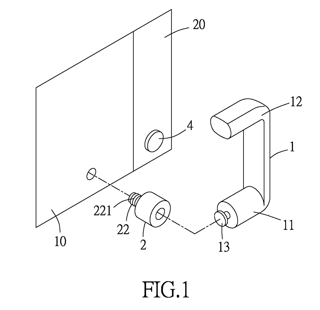
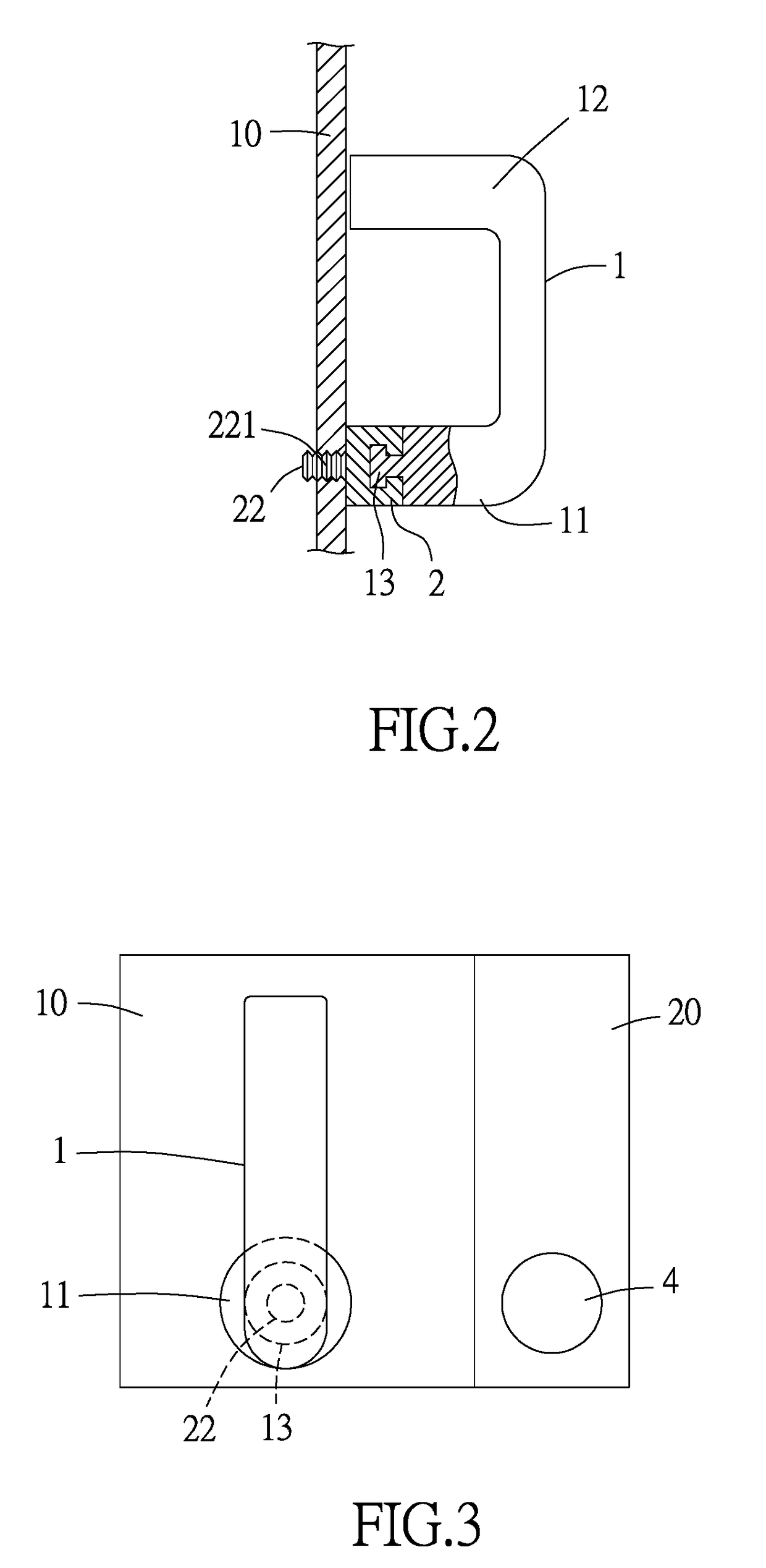
[0097]Please refer to FIGS. 1, 2 and 3. A movable handle according to a first preferred embodiment of the present invention includes a movable member 1, which can be made of a plastic material, a metal material or a composite material; and a seat, which can be made of a plastic material, a metal material or a composite material. The movable member 1 can be configured to include a main body 11 and a bent portion 12. The main body 11 can be a bar-shaped body, a block-like body, a ball-shaped body, a wedge-shaped body or any other suitably shaped body. The bent portion 12 can be bent inward, outward or in any other suitable direction relative to the main body 11. The main body 11 of the movable member 1 is movably a...


PUM


Abstract

A movable handle includes a movable member and a seat, both of which can be made of a plastic, a metal or a composite material. The movable member includes a main body and a bent portion. The main body can be bar-shaped, block-like, ball-shaped, wedge-shaped or in any other suitable shape, and the bent portion can be bent inward, outward or in any other direction relative to the main body. The main body of the movable member is movably assembled to the seat, and the seat is connected to a first object, such that the movable member is indirectly connected to the first object via the seat and can be turned or moved upward and downward or leftward and rightward on and relative to the first object.

Description

CROSS-REFERENCE TO RELATED APPLICATION[0001]This non-provisional application claims priority under 35 U.S.C. §119(a) on Patent Application No(s). 105202437 filed in Taiwan, R.O.C. on Feb. 19, 2016, the entire contents of which are hereby incorporated by reference.FIELD OF THE INVENTION[0002]The present invention relates to a handle, and more particularly, to a movable handle having a seat, which is connected to a first object, and a movable member assembled to the seat and can be turned or moved upward, downward, leftward or rightward relative to the seat.BACKGROUND OF THE INVENTION[0003]Conventionally, the mounting structure on a handle for connecting the handle to a chassis of an electric product or some other object usually includes a threaded hole provided near an end of the handle and a through hole provided on the chassis or the object. A screw is extended from a rear side of the through hole to be locked to the threaded hole on the handle, such that the handle is fixed to the...

Claims


Application Information

Patent Timeline
Patent Type & Authority Applications(United States)
IPC IPC(8): G05G1/04G05G5/04G05G7/00G05G5/05
CPCG05G1/04G05G7/00G05G5/04G05G5/05H05K7/00H05K7/1411
Inventor WANG, TING-JUILIAO, CHIA-CHING
Owner FIVETECH TECH INC
Why Eureka
Try Eureka