Switch device

a switch device and switch technology, applied in the direction of emergency actuators, contact mechanisms, electrical devices, etc., to achieve the effect of increasing the operation reliability of the switch device and preventing erroneous operation

Active Publication Date: 2017-05-16
FUJI ELECTRIC FA COMPONENTS & SYST CO LTD +1
View PDF12 Cites 3 Cited by
  • Summary
  • Abstract
  • Description
  • Claims
  • Application Information

AI Technical Summary

Benefits of technology

[0023]The invention is provided to resolve the aforementioned problems, and it is an objective of the invention to provide a switch device with a high operation reliability in which opening-closing contact portions are not erroneously opened or closed even when an impact is applied to the switch device from the outside.
[0031]Further, the opening-closing contacts of the opening-closing contact mechanism are urged at all times in the direction to be in the opening-closing state at the time the operation unit is in the standby state, that is, in the direction in which the movable contacts and the fixed contacts are closed in the case of a normally closed contact structure and in the direction in which the movable contacts and the fixed contacts are separated from each other in the case of a normally open contact structure. Therefore, even when an impact is applied to the switch device in the standby state, the movable contacts are unlikely to move. As a consequence, erroneous operation is prevented and operation reliability of the switch device can be increased.

Problems solved by technology

In the switch device having a normally open arrangement such that the opening-closing contacts are open in the standby state, an impact force can erroneously close the fixed contacts with the movable contacts, regardless of the operator's intentions, thereby causing a switch-on state.

Method used


Image

  • Switch device
  • Switch device
  • Switch device

Examples


Embodiment Construction

[0046]An embodiment of the invention will be explained hereinbelow in detail with reference to the drawings.

[0047]FIGS. 1 to 11 depict an example of the switch device to be used as a pushbutton switch for emergency stop in accordance with the present embodiment.

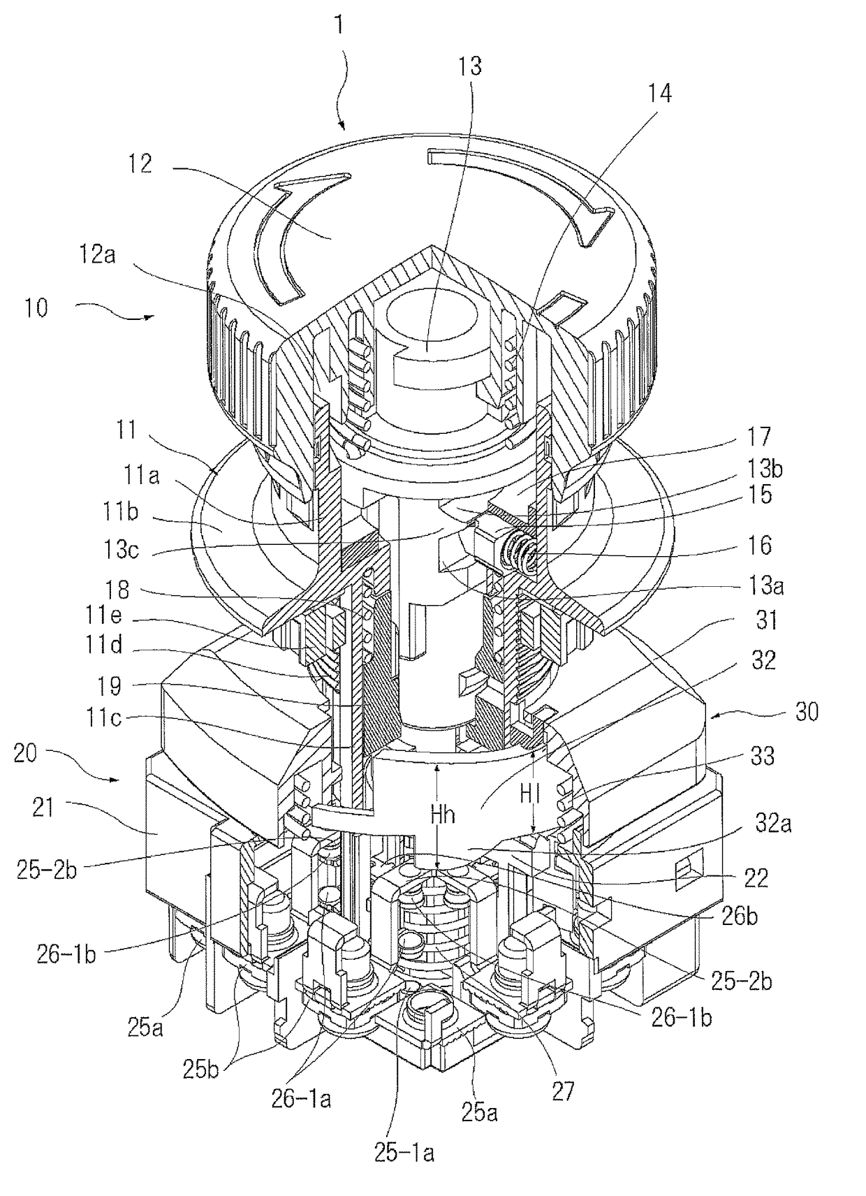
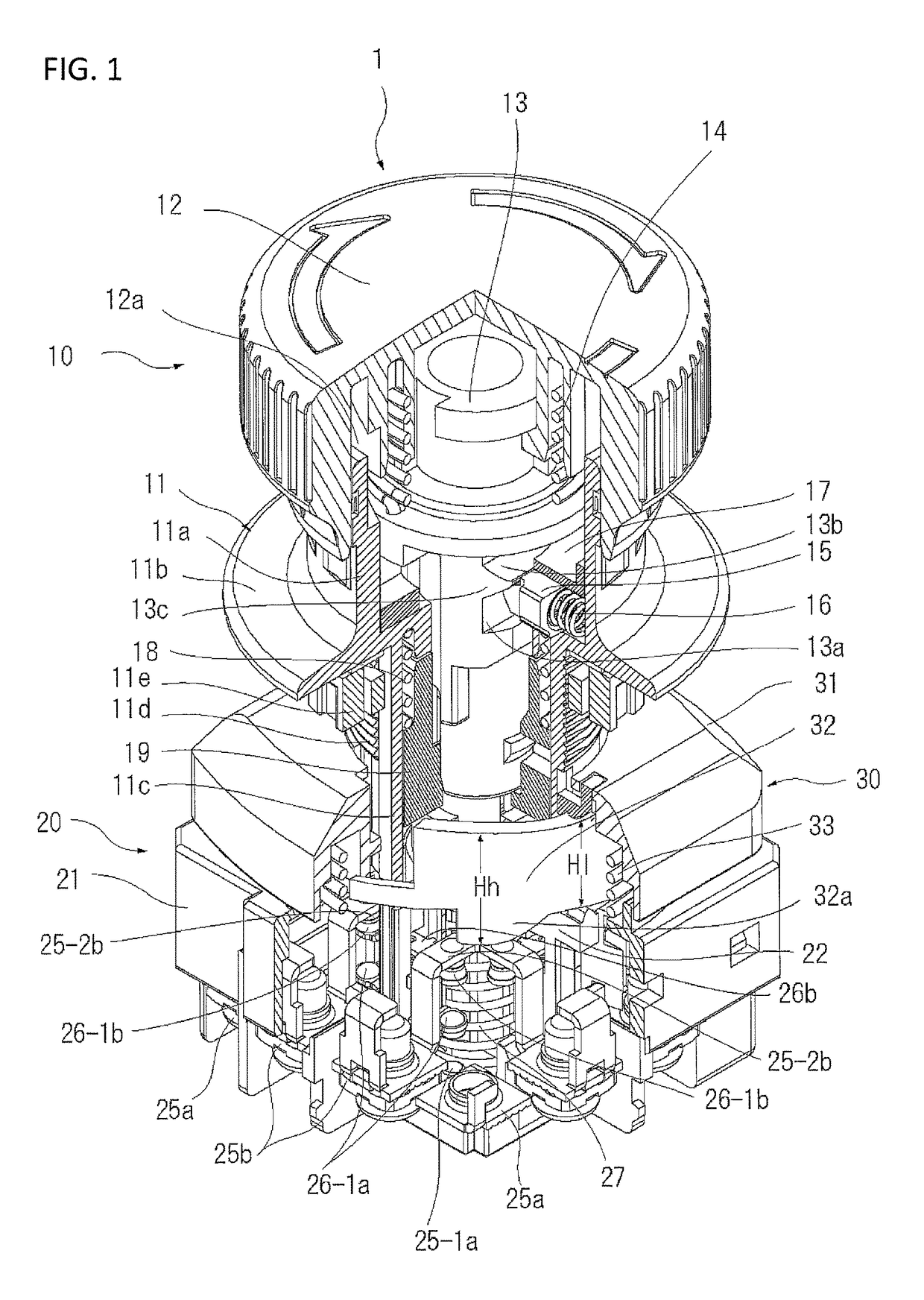
[0048]In FIG. 1, the reference numeral 1 refers to a switch device provided with an operation unit 10 and a switch unit 20 which are arranged to be joinable to each other and separable from each other.

[0049]The operation unit 10 transmits an external operating force to the switch unit 20 and opens / closes an opening / closing contact mechanism located inside the switch unit 20. The operation unit includes a pushbutton 12 and an operation unit main body 11 that supports the pushbutton.

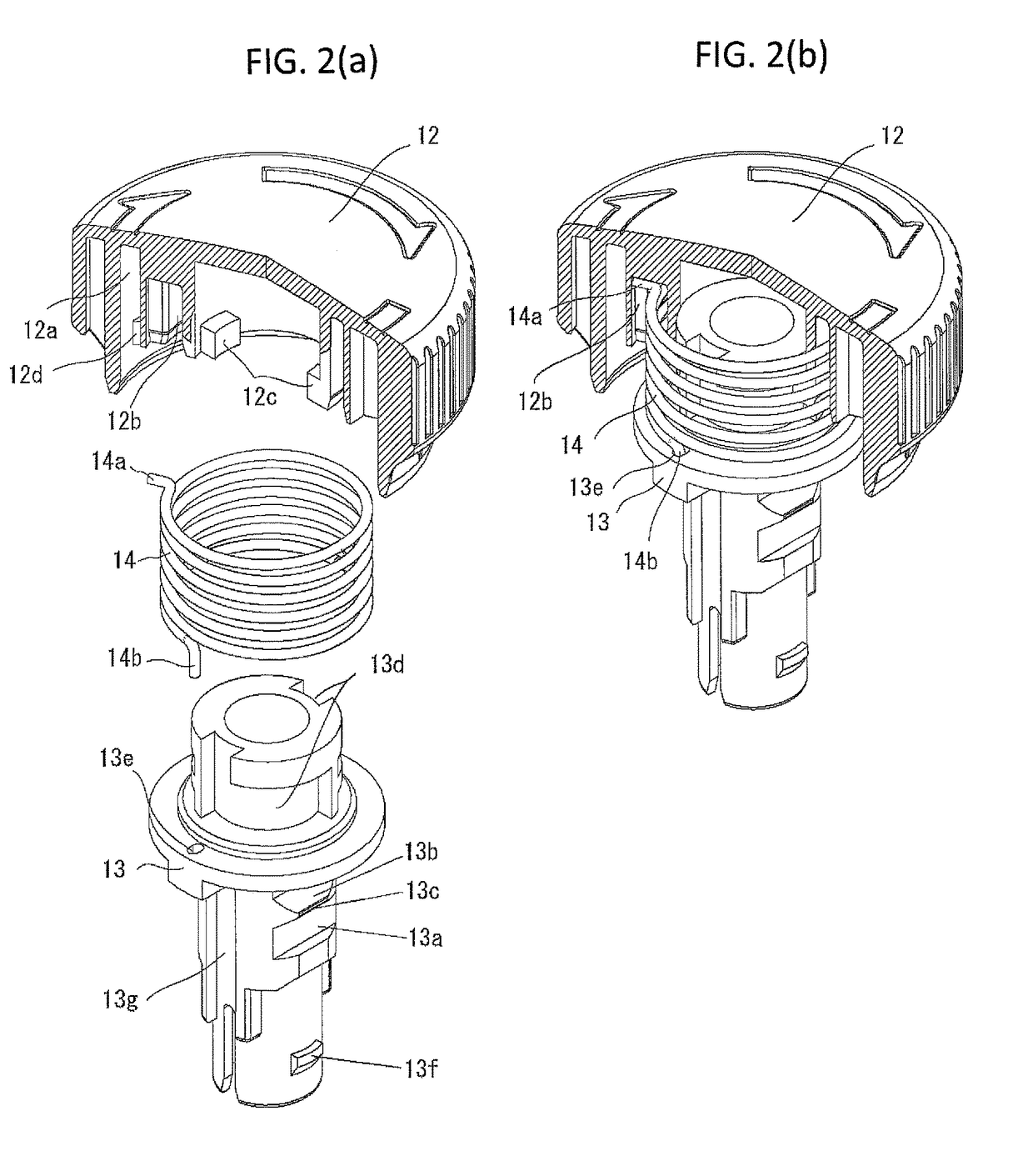
[0050]As shown in detail in FIG. 2, the pushbutton 12 is assembled with a push rod 13 through a pushbutton return spring 14 constituted by a twisted coil spring.

[0051]When the aforementioned components are assembled, initially, a bent portion 14a at...


PUM


Abstract

A switch device includes an operation unit having a pushbutton for performing a pushing operation; a switch unit separably joined to the operation unit, the switch unit including an opening-closing contact mechanism opened or closed in conjunction with the pushing operation of the pushbutton of the operation unit, and a rotary drive plate rotating between a standby position and a usage position; and an engagement portion engaging the operation unit to the rotary drive plate to rotary-drive the rotary drive plate from the standby position to the usage position when the operation unit is attached to the switch unit. The operation unit is detached from or attached to the switch unit to set the opening-closing contact mechanism in respectively predetermined opening-closing states.

Description

CROSS-REFERENCES TO RELATED APPLICATIONS[0001]This is continuation application of a PCT International Application No. PCT / JP2013 / 083155 filed Dec. 11, 2013, which claims priority of Japanese Application No. 2013-019361 filed Feb. 4, 2013, the disclosure of which is incorporated herein.TECHNICAL FIELD[0002]The invention relates to a switch device, in which an operation unit used in a state of attachment to a panel, or the like, and a switch unit, in which an opening-closing contact is opening-closing operated by the operation unit, are structured to be separable from each other.BACKGROUND ART[0003]For example, Patent Literature 1 describes a known switch device in which an operation unit and a switch unit operated by the operation unit are structured to be separable.[0004]A conventional switch device 1 described in Patent Literature 1 is depicted in FIGS. 12 to 14.[0005]A switch device 100 is provided with an operation unit 110 and a switch unit 120 which are structured mutually atta...

Claims


Application Information

Patent Timeline
Patent Type & Authority Patents(United States)
IPC IPC(8): H01H3/62H01H3/02H01H25/00H01H13/62H01H13/14
CPCH01H25/008H01H3/022H01H13/62H01H13/14H01H2003/0246H01H2221/01H01H2221/036
Inventor SHIMOYAMA, EIJIROUTAKANO, YOSHIHIROMACHIDA, NORIYOSHI
Owner FUJI ELECTRIC FA COMPONENTS & SYST CO LTD
Why Eureka
Try Eureka