Overlifting door latch with locking mechanism

a door latch and locking mechanism technology, applied in the field of door latches, can solve the problem that the rotary member cannot rotate, and achieve the effect of simple construction and high operational reliability

Active Publication Date: 2019-01-17
EMZ HANAUER
View PDF0 Cites 9 Cited by
  • Summary
  • Abstract
  • Description
  • Claims
  • Application Information

AI Technical Summary

Benefits of technology

[0006]It is an object of the invention to equip an overlifting door latch with a suitable locking mechanism so that it is suitable for use in a washing machine. The door latch is to have as simple a construction as possible while having high operational reliability.

Problems solved by technology

However, because the locking member is in its locking position, the rotary member cannot rotate as far as the release rotational position.

Method used


Image

  • Overlifting door latch with locking mechanism
  • Overlifting door latch with locking mechanism
  • Overlifting door latch with locking mechanism

Examples


Embodiment Construction

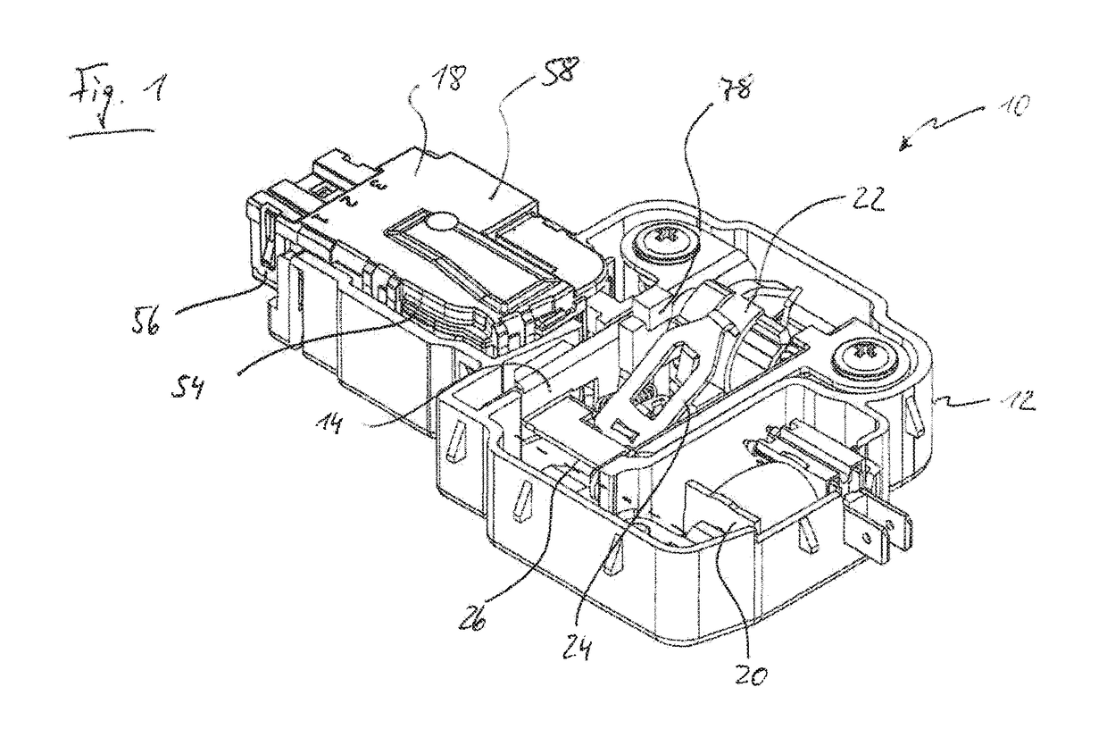
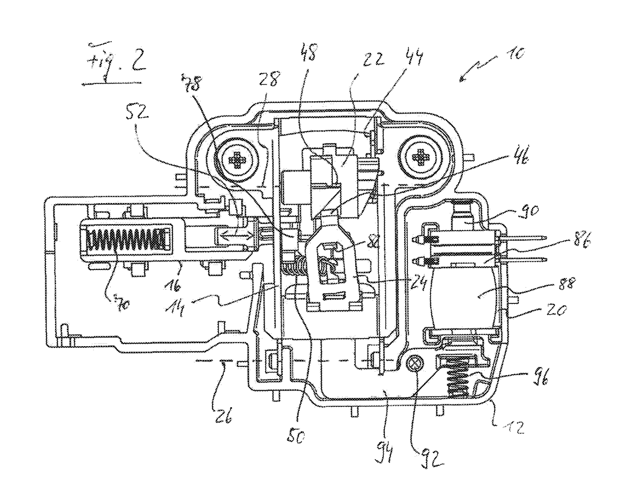
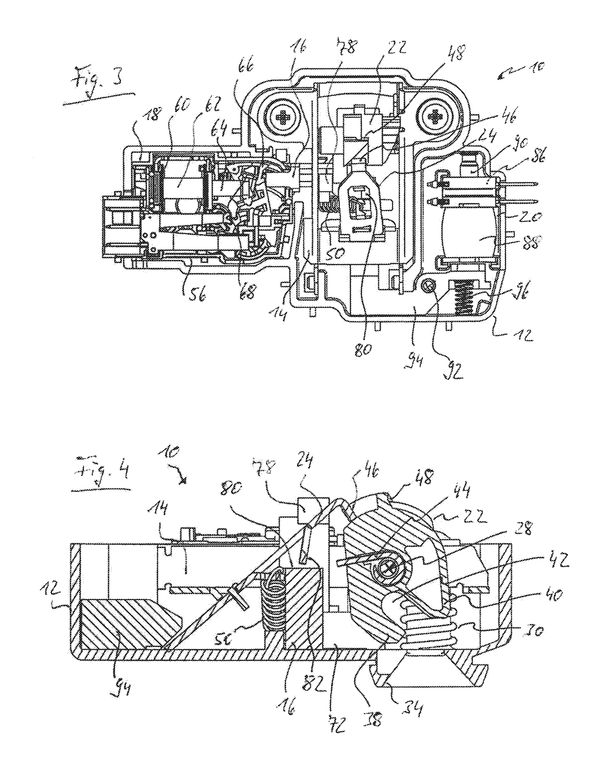
[0032]The door latch generally designated 10 in the figures has a multi-part latch housing 12 in which a carrier lever 14, a locking slider 16 (see in particular FIG. 2), a locking module 18 and an opening unit 20 are accommodated as the main components. A rotary member 22 and a catch 24 which is pivotable in at least two movement directions are additionally mounted on the carrier lever 14. In the region of one of its lever ends, the carrier lever 14 is mounted on the latch housing 12 to be pivotable about a pivot axis 26. The rotary member 22 is mounted on the carrier lever 14 to be rotatable about a rotation axis 28 which is parallel to the pivot axis 26 and stationary relative to the carrier lever 14. By means of a pair of spring elements (here: helical compression springs) 30 (see FIGS. 4, 6 and 7) arranged axially on either side of the rotary member 22, the carrier lever 14 is biased into a rest position, from which it can be pivoted, for the purposes of emergency opening, abou...


PUM


Abstract

A door latch for an electrical domestic appliance includes a rotary member rotationally movable in a rotation plane between a closing rotational position and a release rotational position, a movably arranged catch for arresting engagement by an overlifting rotational movement of the rotary member with the rotary member in its closing rotational position, and a locking assembly having a locking member movable between an unlocking position and a locking position. The rotary member is spring-biased towards the release rotational position and which, in the closing rotational position, holds a closure member to keep a door closed and, in the release rotational position, releases the closure member in order for the door to open. The locking member forms a first blocking arrangement by means of which the locking member in its locking position blocks the rotary member against rotation out of the closing rotational position into the release rotational position.

Description

BACKGROUND OF THE INVENTION1. Field of the Invention[0001]The present invention relates generally to a door latch for an electrical domestic appliance. Particularly, the present invention relates to a door latch for a laundry treatment appliance.2. Description of the Prior Art[0002]The door latches considered within the context of the present disclosure comprise a rotary member which is arranged to be rotationally movable in a rotation plane between a closing rotational position and a release rotational position and is spring-biased in the direction towards the release rotational position and which, in the closing rotational position, holds a closure member in order to keep a door of the domestic appliance closed and, in the release rotational position, releases the closure member in order for the door to open. The door latches of the type under consideration here further comprise a movably arranged catch for arresting engagement, which is releasable by an overlifting rotational mov...

Claims


Application Information

Patent Timeline
Patent Type & Authority Applications(United States)
IPC IPC(8): D06F39/14E05B47/06D06F37/42
CPCD06F39/14D06F37/42E05B47/0607E05C3/165E05C3/24E05Y2900/312E05B47/0603E05B63/0056E05C19/022E05B2047/0008E05B2047/0081
Inventor DIRNBERGER, ALBERTWALZ, DOMINIK
Owner EMZ HANAUER
Why Eureka
Try Eureka