
Sensor unit-actuating mechanism and liquid crystal display device provided with sensor unit-actuating mechanism

a technology of sensor unit and actuator, which is applied in the direction of material analysis through optical means, optical radiation measurement, instruments, etc., can solve the problems of large mechanism scale, design limitation, and impaling designability, and achieve high operation reliability, reduce stroke displacement, and high operation reliability

Active Publication Date: 2013-08-22
EIZO
View PDF0 Cites 10 Cited by
  • Summary
  • Abstract
  • Description
  • Claims
  • Application Information

AI Technical Summary

Benefits of technology

The present invention provides a sensor unit actuating mechanism using a shape-memory alloy wire which has high operation reliability and is energy-saving. The mechanism allows the sensor unit to smoothly move in and out of its frame without losing stroke displacement. It also has a mechanism to relax external force and prevent direct damage to the shape-memory alloy wire. The actuator is energy-efficient and can be linearly moved without excessive heat dissipation. The sensor unit can smoothly leave or enter the frame and is insusceptible to prank by children or the like. The mechanism is thin and inconspicuous when placed on thinner devices, such as liquid crystal display devices. Overall, the present invention provides a thin and reliable actuating mechanism for sensors in various devices.

Problems solved by technology

Accordingly, it is desired to prevent the sensor unit actuating mechanism from restricting the appearance and shape of the liquid crystal display device and thus impairing designability.
This makes the mechanisms large-scale.
In other words, there is a need to reserve space for housing the electric motor and the drive transmission mechanism, thereby forming a design limitation.
Further, an increase in the size of the sensor unit actuating mechanism for screen measurement affects the designability of the liquid crystal display device.
However, these Patent Documents do not disclose any specific applications or the like except for such a configuration.

Method used


Image

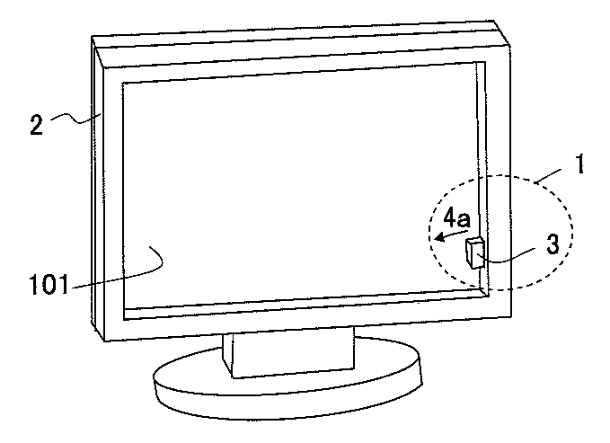
  • Sensor unit-actuating mechanism and liquid crystal display device provided with sensor unit-actuating mechanism
  • Sensor unit-actuating mechanism and liquid crystal display device provided with sensor unit-actuating mechanism
  • Sensor unit-actuating mechanism and liquid crystal display device provided with sensor unit-actuating mechanism

Examples


first embodiment

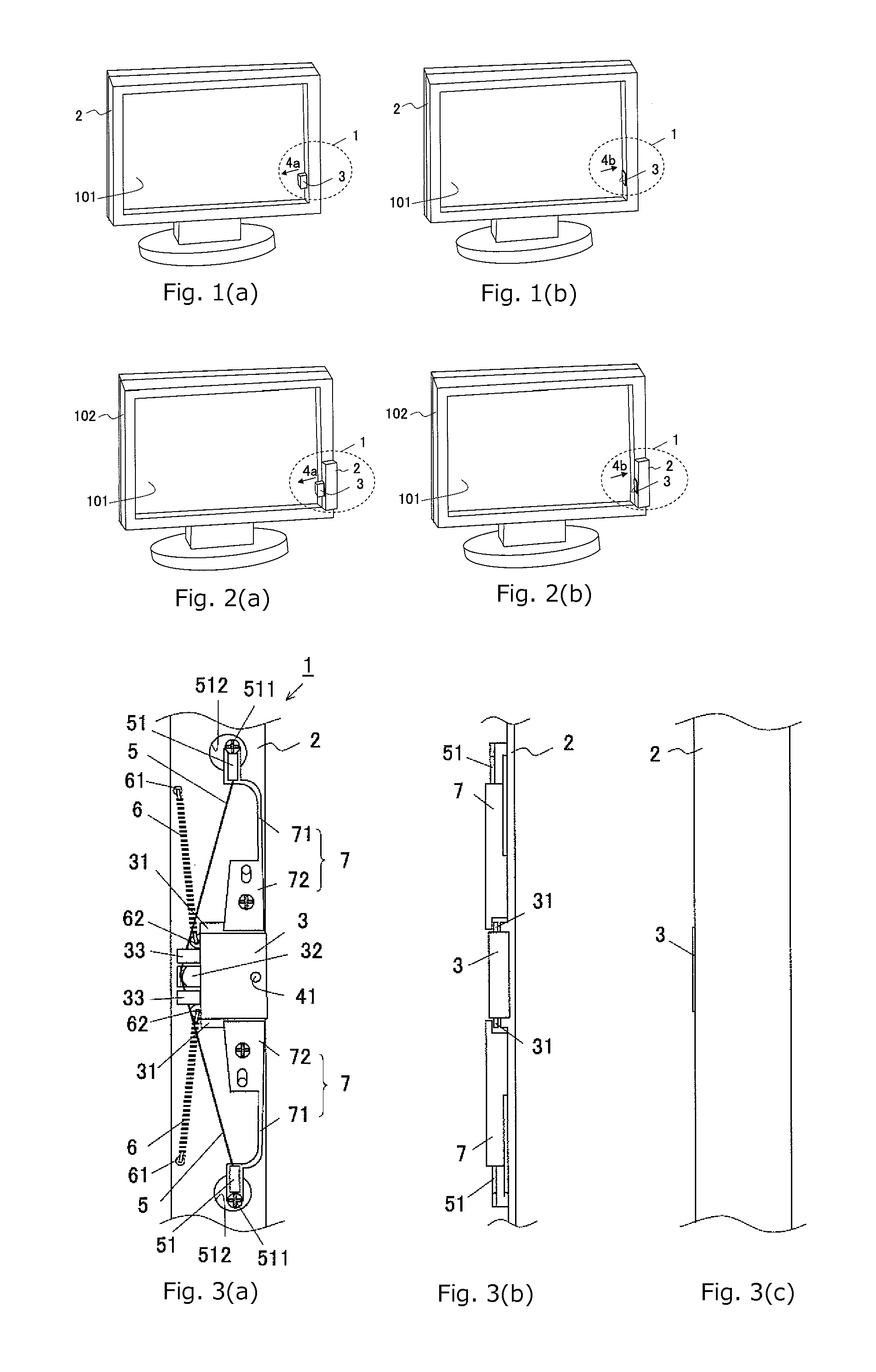
[0073]FIGS. 3(a) to 3(b) show structural diagrams illustrating a sensor unit actuating mechanism 1 of a first embodiment of the present invention. FIG. 3(a) is a rear view seen from inside, FIG. 3(b) a side view, and FIG. 3(c) a front view seen from outside. As used herein, the rear view seen from inside refers to a diagram when viewing the user from the monitor screen 101, and the front view seen from outside is a diagram when viewing the monitor screen 101 from the user. For the sake of description, the horizontal direction in the rear view is defined as an X direction, and the vertical direction therein as a Y direction.

[0074]A rectangular, planar sensor unit 3 of the sensor unit actuating mechanism 1 of the present embodiment is disposed on a bezel (frame) 2, and planar protruding members 31 serving as slide rails are integrally mounted on both sides of the sensor unit 3 (on the upper and lower sides thereof in FIG. 3(a)). A pair of arcuate members 7 serving as balance members a...

second embodiment

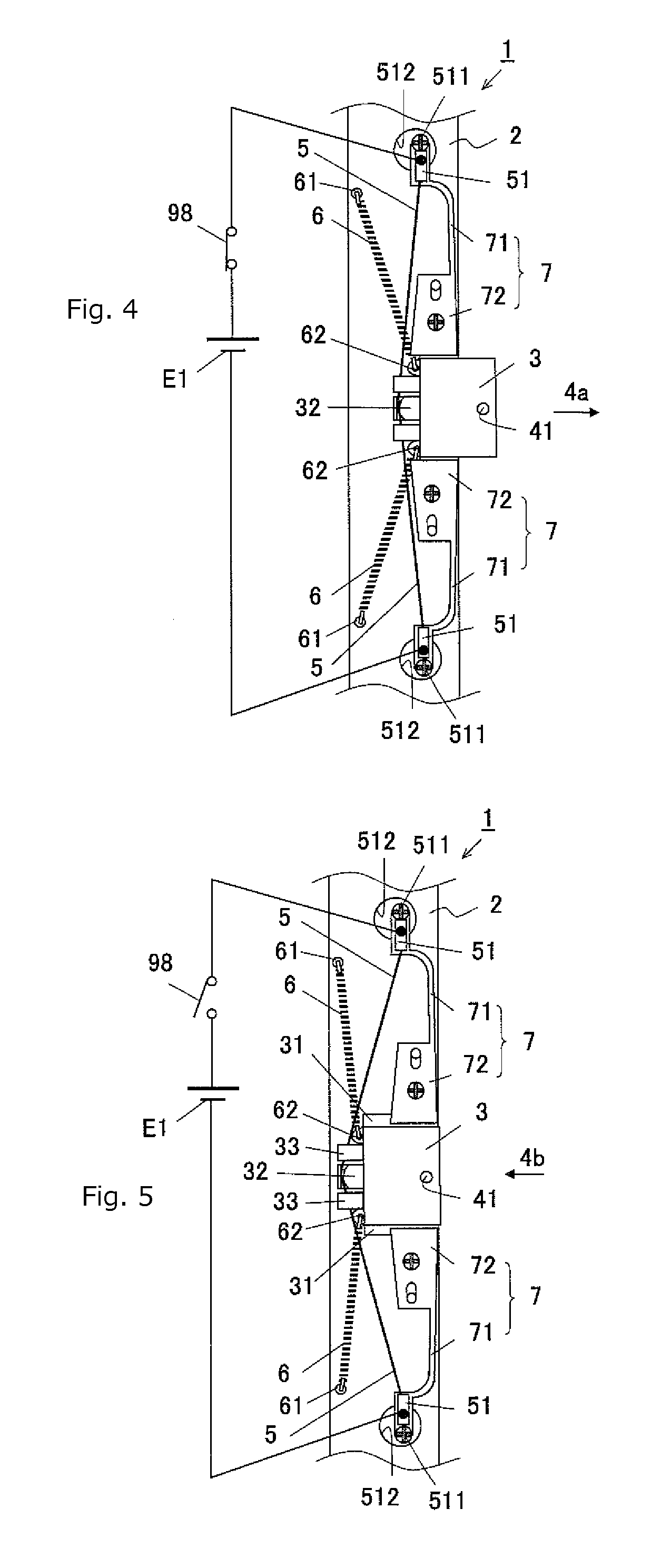
[0083]FIG. 7 is a structural diagram illustrating a sensor unit actuating mechanism 1 of a second embodiment of the present invention and is a rear view seen from inside. The same reference numerals denote the same functions and therefore description thereof will be omitted as appropriate. In the sensor unit actuating mechanism 1 of the second embodiment shown in FIG. 7, the component disposition surface of the frame 2 and the surfaces of the arcuate members 7 have conductivity. Thus, the electrode terminals 51 and an electrode terminal 53 are electrically connected together. Disposed in the center of the rear end of the sensor unit 3 is an electrode terminal 52 which is electrically connected to a middle portion of the shape-memory alloy wire 5.

[0084]FIG. 8 is a diagram showing a state where the shape-memory alloy wire 5 included in the sensor unit actuating mechanism of the present embodiment is energized. A line drawn from the electrode terminal 53 which is electrically connected...

third embodiment

[0085]FIGS. 11(a) to 11(c) show structural diagrams illustrating the sensor unit actuating mechanism 1 of a third embodiment of the present invention. FIG. 11(a) is a rear view seen from inside, FIG. 11(b) a side view, and FIG. 11(c) a front view seen from outside. As used herein, the rear view seen from inside refers to a diagram when viewing the user from the monitor screen 101, and the front view seen from outside is a diagram when viewing the monitor screen 101 from the user. For the sake of description, the horizontal direction in the rear view is defined as an X direction, and the vertical direction therein as a Y direction. The same reference numerals denote the same functions and therefore description thereof will be omitted as appropriate.

[0086]In the sensor unit actuating mechanism 1 for screen measurement of the present embodiment, the rectangular, planar sensor unit 3 is disposed in the bezel (frame) 2, and planar protruding members 31 serving as slide rails are integral...


PUM


Abstract

A novel sensor unit actuating mechanism that can cause a sensor unit to leave or enter a frame smoothly even when the thickness of the frame is reduced and that has a mechanism for coping with a prank by a child or the like, such as a push-back of the sensor unit, The sensor unit actuating mechanism includes a frame, a sensor unit including an optical sensor, a spring member configured to expand or contract in a Y direction, actuators configured to contract against the resilience of the spring member when energized, and a guide member for moving the sensor unit linearly in an X direction. When the actuator is energized, the sensor unit, is linearly moved from inside the frame to the measurement position; when the actuator is energized, the sensor unit is linearly moved from the measurement position to inside the frame and stored therein.

Description

TECHNICAL FIELD[0001]The present invention relates to a sensor unit actuating mechanism configured to move, to a predetermined measurement position, a sensor unit including a sensor for measuring a physical quantity from an object to be measured, and a liquid crystal display device including the sensor unit actuating mechanism.BACKGROUND ART[0002]Image display monitors are being used not only in offices or households but also at sites of various kinds of professional work, such as graphic design and medical care. In particular, high-end liquid crystal monitors are being used to display a graphic design image or medical diagnostic image, since display of such images requires high-definition image quality having high reproducibility. Such a liquid crystal monitor, which is required to provide high-definition image quality having high reproducibility, attempts to enhance the reproducibility of display images by measuring an optical property of a liquid crystal screen, such as luminance...

Claims


Application Information

Patent Timeline
Patent Type & Authority Applications(United States)
IPC IPC(8): G01J1/04
CPCG01D11/24G01J1/0403
Inventor HOGO, HIDEKAZUKITAMURA, MAKOTO
Owner EIZO
Learn More