Position detection arrangement for a moveable functional element which can be positioned motor-driven in a motor vehicle

a functional element and position detection technology, applied in the direction of wing accessories, process and machine control, instruments, etc., can solve the problems of comparatively low accuracy which can be achieved with pulse counting, control engineering effort to implement it is comparatively high, and the control of motorized positioning can only be as good. , to achieve the effect of high operating reliability and compact construction

Inactive Publication Date: 2009-03-19
BROSE SCHLIESSSYSTEME GMBH & CO KG
View PDF7 Cites 11 Cited by
  • Summary
  • Abstract
  • Description
  • Claims
  • Application Information

AI Technical Summary

Benefits of technology

[0015]A primary object of the invention is to embody and develop the known position detection arrangement such that detection of the absolute position of the functional element can be achieved with high operating reliability and compact construction.

Problems solved by technology

It is apparent that the control of motorized positioning can only be as good as the position data present in the control means about the current absolute position of the functional element.
The problem of the known position detection arrangement is, first of all, the fact that the accuracy which can be achieved with pulse counting is comparatively low.
In addition, the control engineering effort to implement it is comparatively high.
Finally, in these systems problems often occur in an emergency, for example, when the voltage supply fails.
The disadvantage in angle encoders is always the high costs.

Method used


Image

  • Position detection arrangement for a moveable functional element which can be positioned motor-driven in a motor vehicle
  • Position detection arrangement for a moveable functional element which can be positioned motor-driven in a motor vehicle
  • Position detection arrangement for a moveable functional element which can be positioned motor-driven in a motor vehicle

Examples


Embodiment Construction

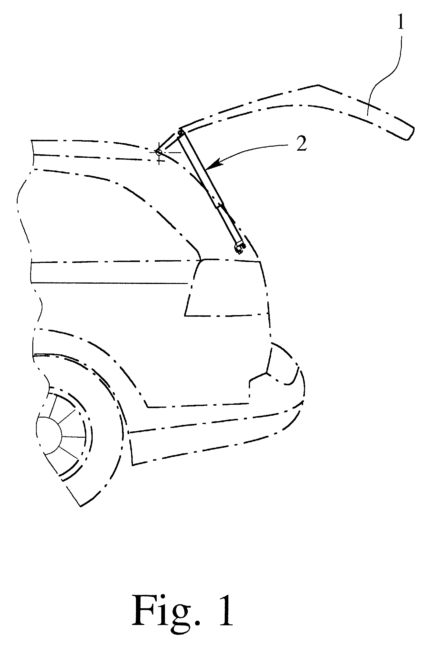
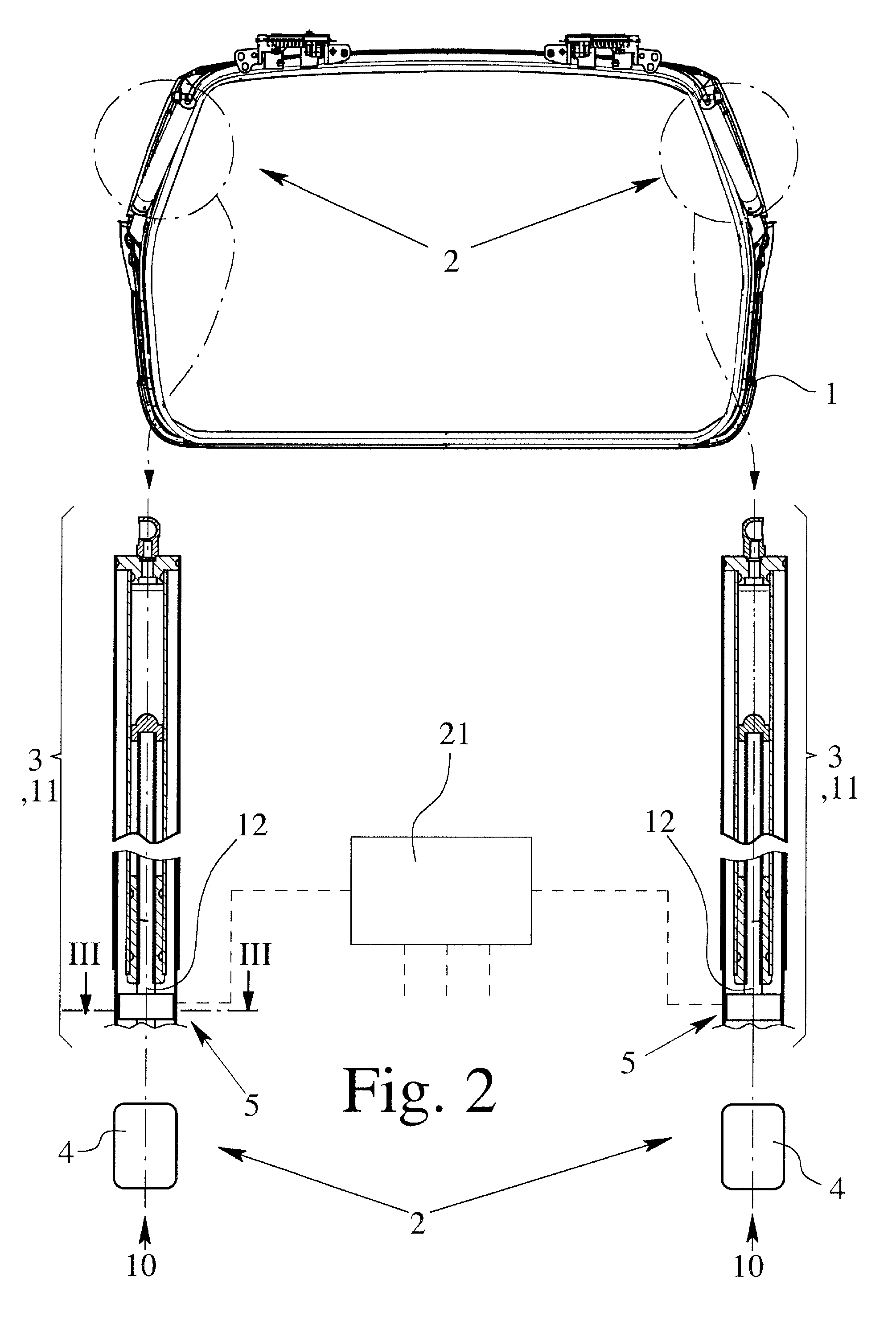
[0031]The position detection arrangement in accordance with the invention can be used for all possible functional elements 1, especially closure elements in a motor vehicle. For this purpose reference is made to the listing of applications in the introductory part of the description, the application to tailgates and side doors being emphasized. The drawings relate to the use of the position detection arrangement for a functional element 1 which is made as a tailgate. This should not be interpreted as limiting. All aspects pointed out in the following description concerning the tailgate 1 completely apply for all other functional elements 1 noted above.

[0032]The tailgate 1 shown in the drawings can be positioned motor-driven. For this a drive arrangement 2 is coupled via a drive train 3 to the tailgate 1 for enabling the tailgate 1 to be positioned by a motor 4.

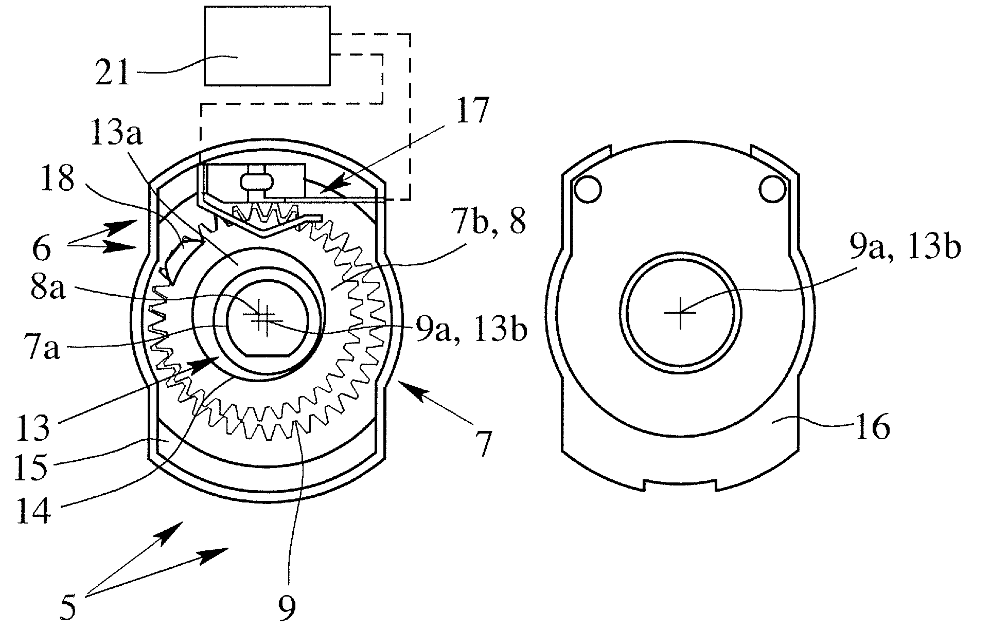
[0033]In order to detect the absolute position of the tailgate 1 a position detection arrangement is proposed. Concerning th...


PUM


Abstract

A position detection arrangement for a functional element (1) which can be positioned motor-driven in a motor vehicle, a drive arrangement (2) being coupled via a drive train (3) to the functional element (1) and the functional element (1) thus being positionable by a motor (4), there being a measuring unit (5) which is assigned to the drive train (3) and which includes a sensor unit (6) and a gearing with a drive side and a driven side, the drive side being assigned to the drive train (3) and the driven side being assigned to the sensor unit (6). It is suggested that the gearing is realized as a tumble gearing (7) with a tumbler gear (8) and a ring gear (9).

Description

BACKGROUND OF THE INVENTION[0001]1. Field of the Invention[0002]This invention relates to a position detection arrangement for a functional element which can be positioned motor-driven in a motor vehicle, a drive arrangement being coupled via a drive train to the functional element and the functional element thus being positionable by a motor, there being a measuring unit which is assigned to the drive train for detecting the position of the functional element, wherein the measuring unit comprises a sensor unit and a gearing with a drive side and a driven side, the drive side being assigned to the drive train and the driven side being assigned to the sensor unit. Furthermore the invention relates to a drive unit in a motor vehicle for a positionable functional element with a drive arrangement for motorized positioning of the functional element and a position detection arrangement for detecting the position of the functional element of the type indicated above. The invention also rel...

Claims


Application Information

Patent Timeline
Patent Type & Authority Applications(United States)
IPC IPC(8): G05D3/00G06F7/00
CPCE05Y2201/618E05Y2201/716E05Y2201/726E05F15/622E05Y2400/326E05Y2800/25E05Y2900/50E05Y2400/324
Inventor ENACHE, CRINABRESCIAMI, DAVESIMKIN, OLEG
Owner BROSE SCHLIESSSYSTEME GMBH & CO KG
Why Eureka
Try Eureka