Optical apparatus equipped with rotation restricting mechanism for lens holding frames

a technology of rotating restricting mechanism and optical apparatus, which is applied in the direction of mountings, instruments, camera body details, etc., can solve the problems of restricted cam groove arrangement and difficulty in realizing even higher zoom magnification, and achieve the effect of reducing the diametrical size of the lens barrel and higher zoom magnification

Active Publication Date: 2017-05-23
CANON KK
View PDF8 Cites 0 Cited by
  • Summary
  • Abstract
  • Description
  • Claims
  • Application Information

AI Technical Summary

Benefits of technology

[0009]The invention provides a mechanism which makes it possible to achieve reduction of the diametrical size of a lens barrel provided for an optical apparatus and the thickness of the optical apparatus, as well as to realize an even higher zoom magnification.
[0011]In a second aspect of the invention, there is provided an optical apparatus comprising a first lens holding frame configured to hold a first lens, a second lens holding frame configured to hold a second lens and disposed rearward of the first lens holding frame, and a third lens holding frame configured to hold a third lens and disposed rearward of the second lens holding frame, wherein the first lens holding frame has a first restricting portion that is brought into engagement with the second lens holding frame, to thereby restrict rotation of the second lens holding frame relative to the first lens holding frame, and wherein the third lens holding frame has a second restricting portion that is brought into engagement with the first restricting portion, to thereby restrict rotation of the first lens holding frame relative to the third lens holding frame.
[0012]According to the invention, it is possible not only to achieve reduction of the size of an optical apparatus, but also to realize a higher zoom magnification.

Problems solved by technology

In the lens barrel, however, since the cam grooves corresponding to the respective lenses are all formed in the inner peripheral surface of the single cam barrel, the arrangement of the cam grooves is restricted.
Further, the third group lens does not move relative to the cam barrel along the optical axis, but advances and retracts together with the cam barrel along the optical axis, and hence the arrangement of the lenses in the optical axis direction and the motion trajectory of each of the lenses are restricted, which makes it difficult to realize an even higher zoom magnification.

Method used


Image

  • Optical apparatus equipped with rotation restricting mechanism for lens holding frames
  • Optical apparatus equipped with rotation restricting mechanism for lens holding frames
  • Optical apparatus equipped with rotation restricting mechanism for lens holding frames

Examples


Embodiment Construction

[0022]The invention will now be described in detail below with reference to the accompanying drawings showing embodiments thereof.

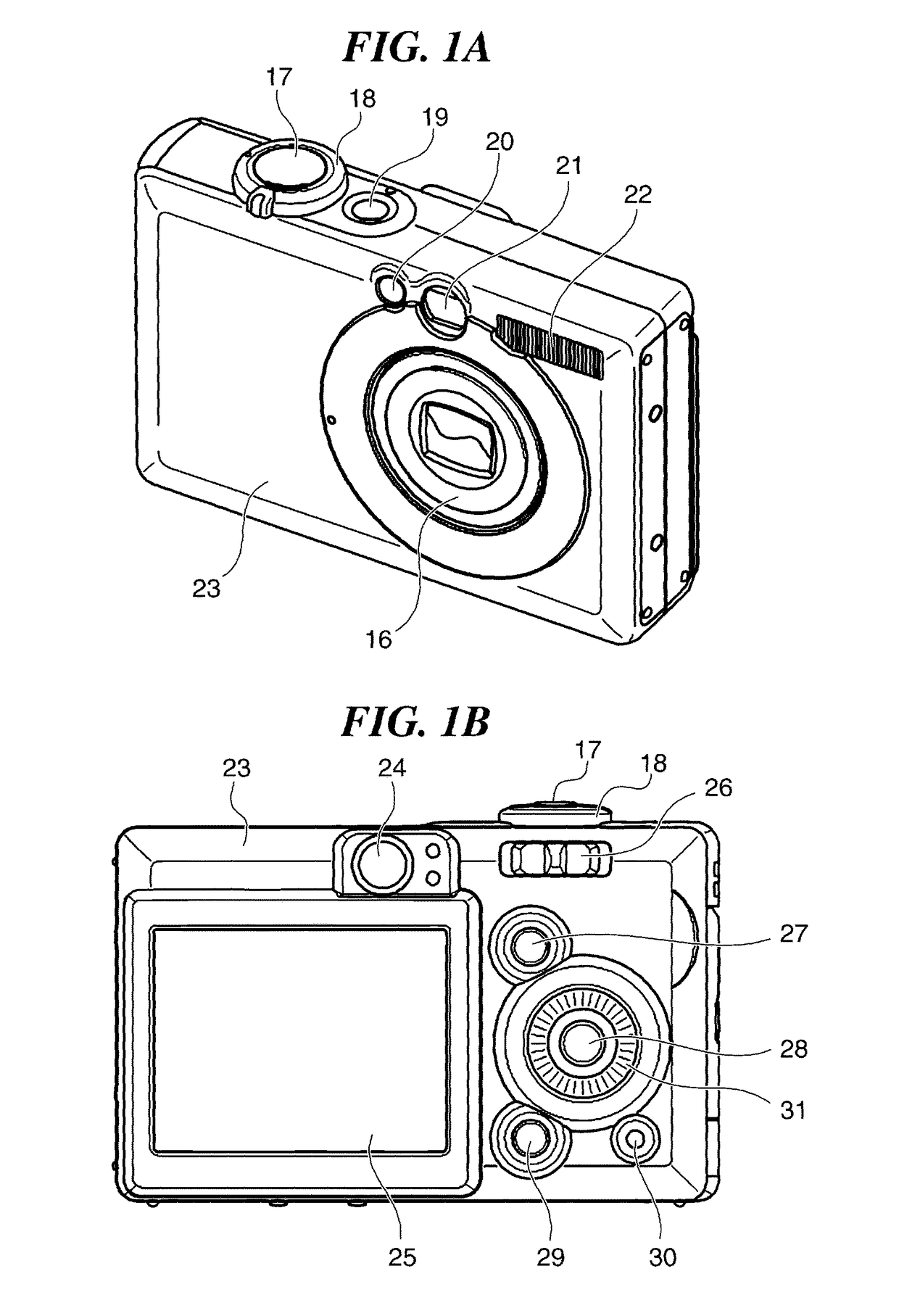
[0023]FIG. 1A is a front perspective view of a digital camera as an example of an optical apparatus equipped with a lens barrel, according to an embodiment of the invention. FIG. 1B is a rear view of the digital camera shown in FIG. 1A.

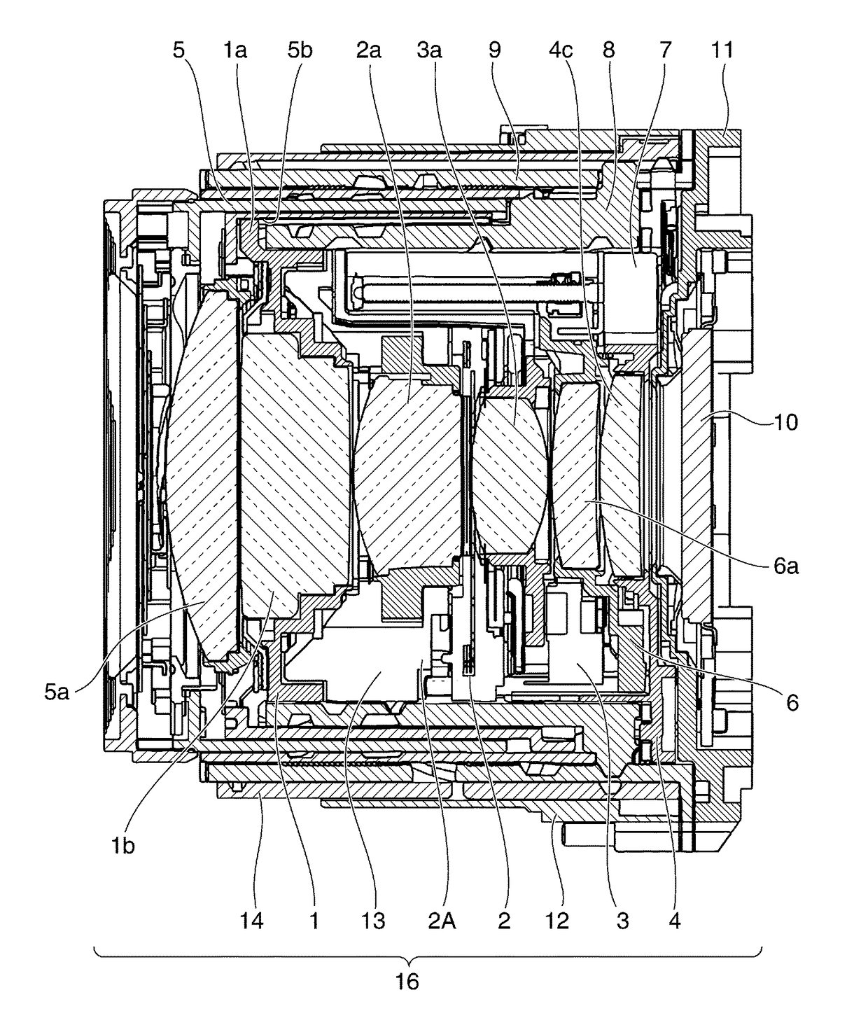
[0024]As shown in FIG. 1A, in a front surface of the digital camera 23, there are arranged a viewfinder 21 for determining a composition of an object, an auxiliary light source 20 for use in photometry and focus detecting, a strobe device 22, and a lens barrel 16. The lens barrel 16 is a zoom type that moves along an optical axis between a shooting position and a retracted position to thereby change a zoom magnification.

[0025]In a top surface of the digital camera 23, there are arranged a release button 17, a power supply switching button 19, and a zoom switch 18. Further, as shown in FIG. 1B, in a rear surface of the digit...


PUM


Abstract

A mechanism which enables reduction of the diametrical size of a lens barrel of an optical apparatus. In the lens barrel, a third group lens unit has a rotation restricted portion. A fourth group lens holder rearward of the third group lens unit has a rotation restricting portion. A sixth group lens holder rearward of the fourth group lens holder has a rotation restricting portion. The rotation restricted portion of the third group lens unit and the rotation restricting portion of the fourth group lens holder are mutually engaged, whereby relative rotation between the lens unit and the lens holder is restricted, and the rotation restricted portion of the third group lens unit and the rotation restricting portion of the sixth group lens holder are mutually engaged, whereby relative rotation between the lens unit and the lens holder is restricted.

Description

BACKGROUND OF THE INVENTION[0001]Field of the Invention[0002]The invention relates to an optical apparatus equipped with a rotation restricting mechanism for a plurality of lens holding frames.[0003]Description of the Related Art[0004]As a lens barrel for an optical apparatus, such as a digital camera, there has been known one which is equipped with a zoom mechanism configured to restrict rotation of each of a plurality of lens holders holding a plurality of lenses by a rectilinear motion barrel and move the lens holders along an optical axis by rotation of a cam barrel, to thereby move the lenses to respective predetermined positions.[0005]Recently, in response to an increasing demand for a higher zoom magnification, a lens barrel tends to have a larger number of lenses and have a longer length in its fully extended state, i.e. the lens barrel tends to have a larger size. On the other hand, there is also a demand for reduction of the thickness of an optical apparatus, and hence it ...

Claims


Application Information

Patent Timeline
Patent Type & Authority Patents(United States)
IPC IPC(8): G02B15/14G03B17/04G02B7/02G02B7/10
CPCG02B7/021G03B17/04G02B7/10G03B2205/0046G03B2217/002
Inventor KUDOH, TOMOYUKI
Owner CANON KK
Why Eureka
Try Eureka