
Compact Axial Turbine for High Density Working Fluid

a technology of working fluid and axial turbine, which is applied in the direction of efficient propulsion technology, machines/engines, mechanical apparatuses, etc., can solve the problems of large system equipment, long response time to initial thermal input, and high cost, and achieve the effect of simplifying fabrication, improving mobility, and reducing turbine siz

Pending Publication Date: 2022-05-12
INDUSTROM POWER LLC
View PDF3 Cites 0 Cited by
  • Summary
  • Abstract
  • Description
  • Claims
  • Application Information

AI Technical Summary

Benefits of technology

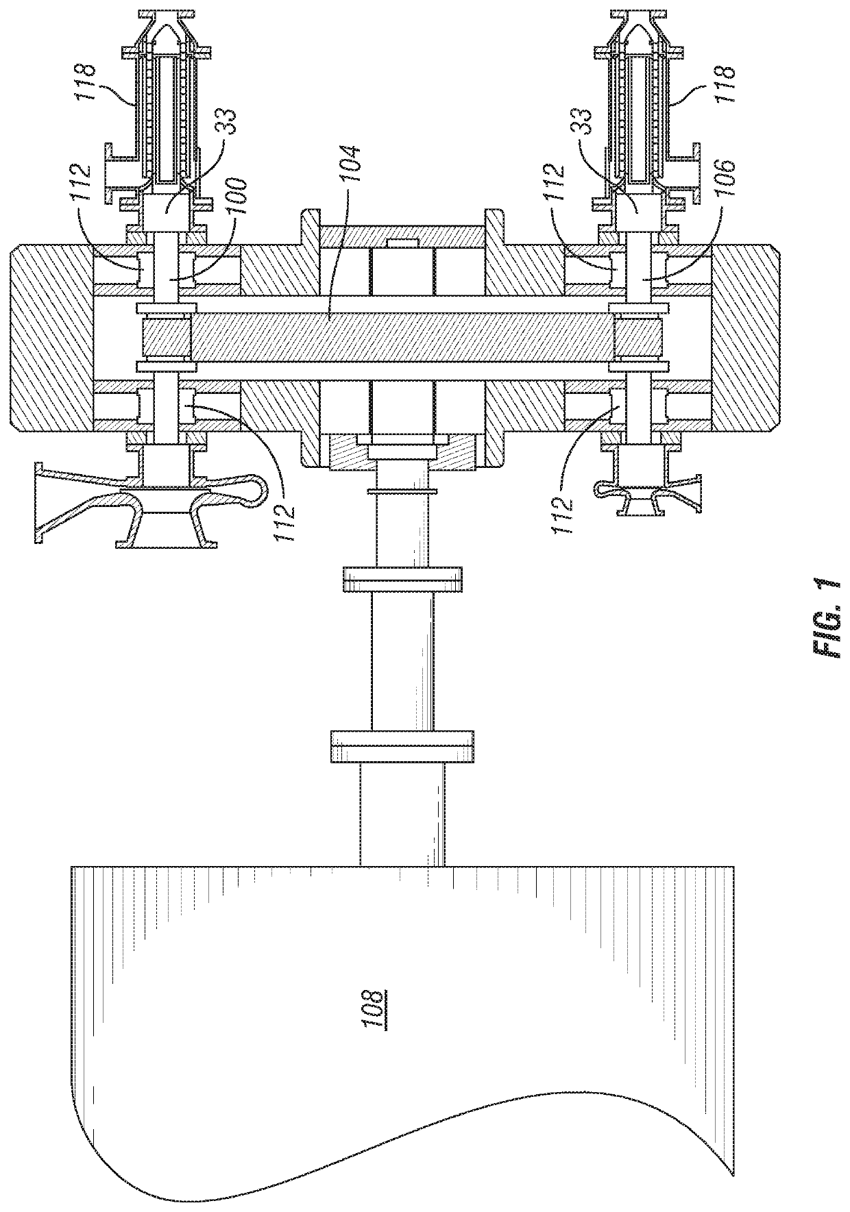
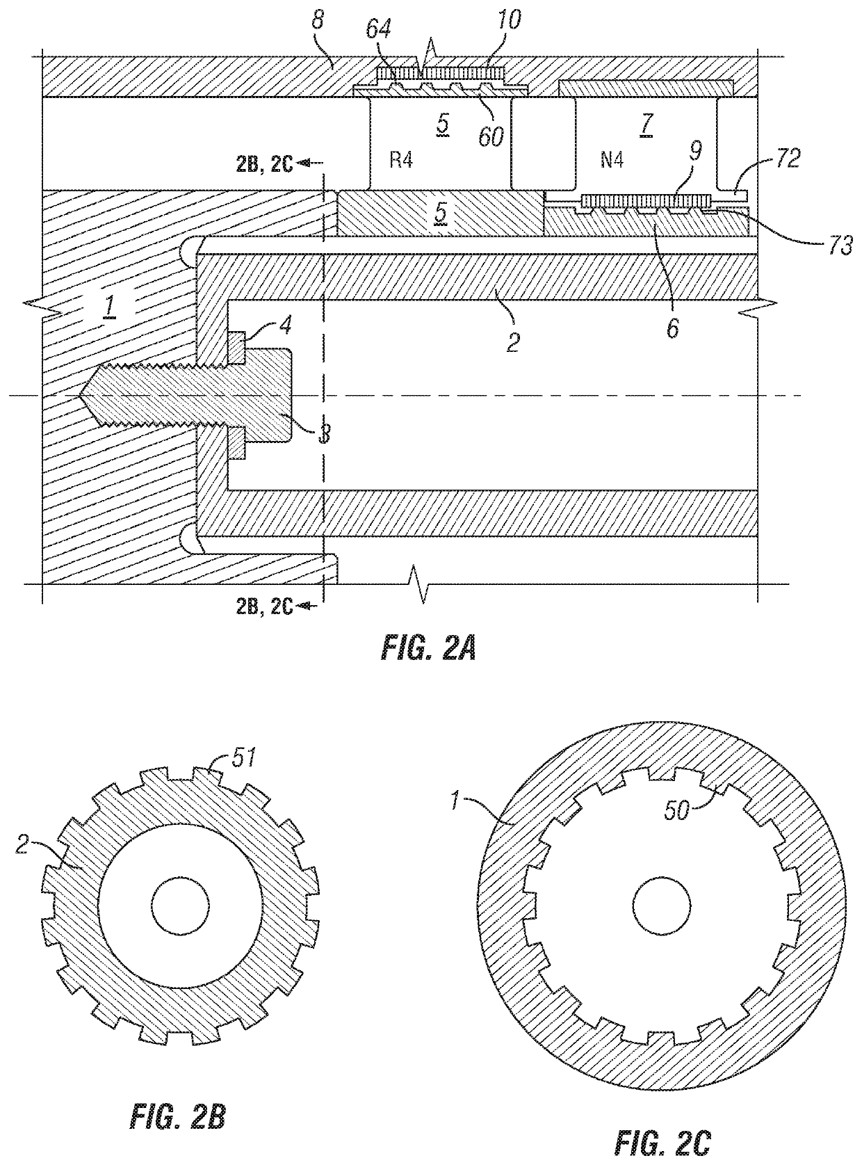
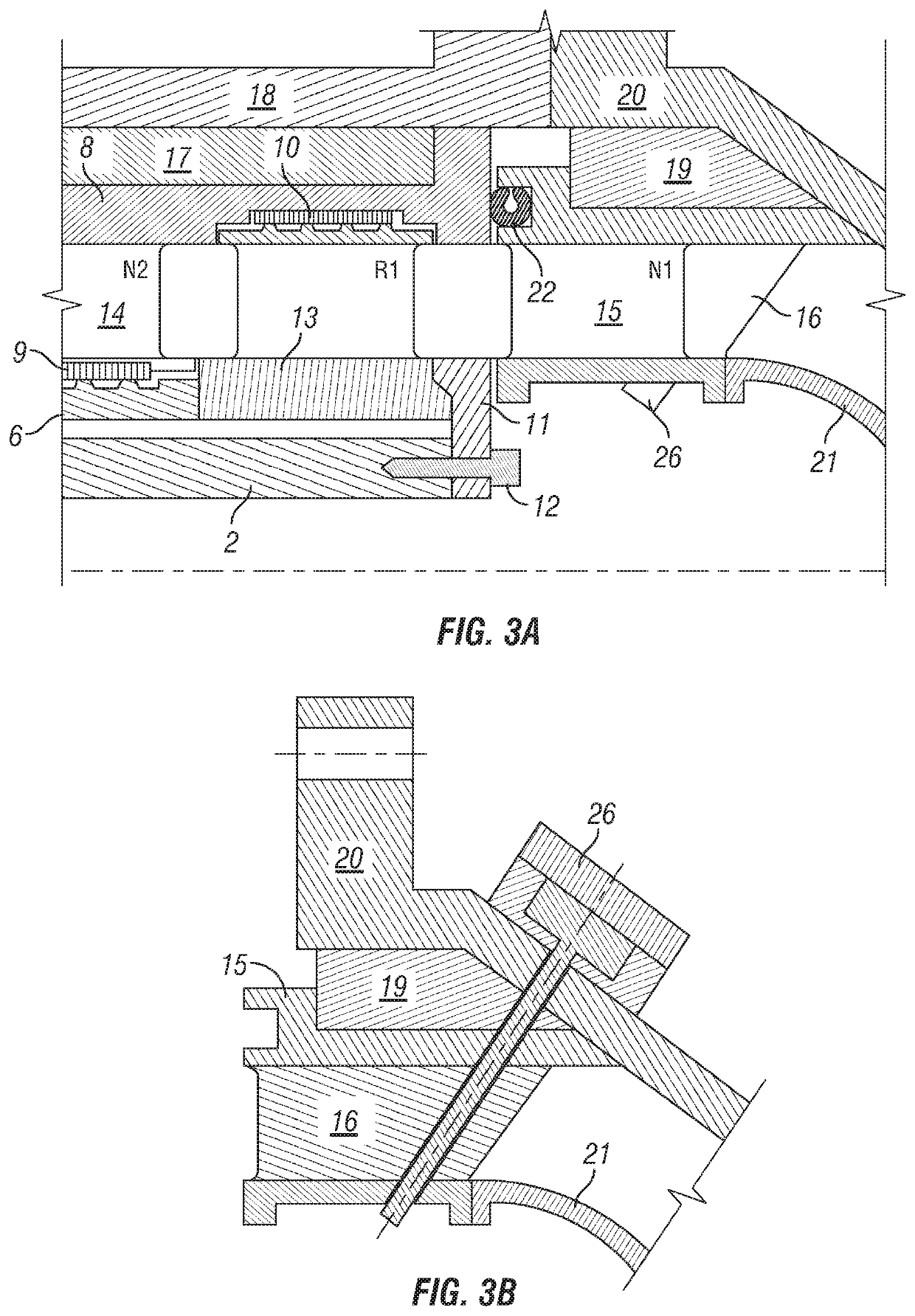
This patent describes a system for more efficient and compact turbines used with high-density working fluids, such as supercritical fluids. The turbines have several features that allow for increased power generation capabilities in smaller size, such as between 10 and 50 megawatts of net power. The design reduces turbine size, simplifies fabrication, improves mobility, and lowering maintenance and repair costs and time. The turbines also have a compact axial design that eliminates certain parts and reduces complexity, weight, and diameter size of the turbine. Certain components are contained within a cartridge that can be easily removed from the turbine casing for maintenance or repair. Overall, this patent provides methods and apparatus to improve high-density working fluid turbine design with the benefit of reducing turbine size, simplifying fabrication, improving mobility, and lowering maintenance and repair costs and time.

Problems solved by technology

They also suffer from a lengthy time of response to initial thermal input into the system.
These conventional systems usually need a waste heat source with temperatures in the range of 500 to 900 degrees C. The system equipment is large-scale, stationary, and costly.
Working fluids for these systems require chemical treatment for water, or use organic hydrocarbon fluids, such as iso-butane, that are not environmentally friendly.
It also requires a significant amount of time to start a conventional heat recovery system—usually 60 minutes, or more.
Miniaturization of mechanical devices, however, is often plagued by fabrication and maintenance issues.

Method used


Image

  • Compact Axial Turbine for High Density Working Fluid
  • Compact Axial Turbine for High Density Working Fluid
  • Compact Axial Turbine for High Density Working Fluid

Examples


Embodiment Construction

[0036]As used herein, “a” and “an” means one or more than one unless otherwise stated. Fasteners known in the art of turbine design include machine bolts, nuts, nut-plates, screws, pins, clips, clamps, retaining wire and equivalents. When fasteners are referenced herein, unless specified otherwise, it should be understood that equivalents may be employed and are considered in the present disclosure.

[0037]Certain components referenced in the drawings herein are repeated within disclosed embodiments. For example, an exemplary embodiment of the present disclosure includes multiple rotors and nozzles. It should be understood that, unless otherwise specified, the description of one repeatable component (including with a particular reference number) applies generally to the rest.

[0038]The invention described herein includes integrally bladed turbine disks known as “blisks.” In particular, it relates to the manner in which a single or plurality of turbine blisks may be combined to form a c...


PUM


Abstract

A compact axial turbine configured to operate with high density working fluid is described. The turbine comprises an axial majority cantilevered turbomachinery shaft. Rotor assemblies and nozzle spacers communicate torque through turbine shaft splines, allowing them to be slid off the shaft for quick replacement in the field. The compact axial turbine houses turbomachinery within a separable inner casing encircled by a cartridge sleeve, thereby forming a cartridge which can itself be removed as a single component.

Description

CROSS-REFERENCE TO RELATED APPLICATIONS[0001]The present application claims priority to U.S. provisional application Ser. No. 61 / 814,821, which was filed on Mar. 6, 2019, entitled Compact Axial Turbine for High Density Working Fluid, the disclosure of which is incorporated by reference herein in its entirety.TECHNICAL FIELD[0002]This invention generally relates to systems and methods for axial turbines for generation of power, such as electricity production or pump or propeller driving or lifting a weight, through the use of a circulating fluid such as supercritical carbon dioxide.BACKGROUND OF THE INVENTION[0003]Many methods and systems exist for generating electricity by the transfer and conversion of heat into mechanical or electrical energy. Systems where the hot source fluid is not recycled, but rather, is discarded or removed by external means (known as waste heat sources) typically have a higher cost per unit of power produced (referred to in the industry as specific cost) an...

Claims


Application Information

Patent Timeline
Patent Type & Authority Applications(United States)
IPC IPC(8): F01D15/12F01D5/10
CPCF01D15/12F05D2260/4031F01D5/10F04D25/045F04D25/163F01D5/066F01D5/34F01D15/10F05D2210/13F05D2220/76F05D2230/61F05D2240/61F05D2260/36F02C1/04F02C1/105Y02T50/60F01D25/265F01D5/06F01D5/027
Inventor ANGEL, PAULHARRIS, JOSEPH
Owner INDUSTROM POWER LLC
Learn More