Automatic analyzers and reagent wheels thereof

a biochemical analyzer and automatic technology, applied in the field of automatic biochemical analyzers and reagent wheels, can solve the problems of inconvenient operation, inability to reach some reagent seats located in the rear side, and the size of the whole equipment, so as to reduce the diametric size and reduce the capacity of the reagent wheel

Active Publication Date: 2017-08-01
SHENZHEN MINDRAY BIO MEDICAL ELECTRONICS CO LTD
View PDF15 Cites 0 Cited by
  • Summary
  • Abstract
  • Description
  • Claims
  • Application Information

AI Technical Summary

Benefits of technology

[0003]This disclosure provides reagent wheels of automatic analyzers that may have both improved capacity and controllable diametric size, thereby meeting the requirements on the capacity and the operability of the analyzers.
[0016]In various embodiments of this disclosure, the automatic analyzer may be equipped with two of the above-described reagent wheels, and based on an overall layout, the two reagent wheels can be arranged one behind the other on a table with respect to an operator. Double-ring reagent wheel can already meet the demand on the capacity of the reagent wheel in high-speed analyzers, and may even have some capacity margin. Therefore, when utilizing such reagent wheel in which the angle can be formed between the symmetrical centerline of the reagent container on the outer ring and the radius of the reagent wheel, the outer-ring capacity of the reagent wheel can be decreased to a certain extent and the diametric size of the reagent wheel can also be reduced effectively, thereby meeting users' demand on the capacity of the reagent wheel and facilitating the uses' operations including picking up or placing down the reagent.
[0017]In order to realize larger test speed, two sets of test systems may usually be integrated into a single high-end automatic analyzer. In this case, one common method is to have the reagent on inner and outer rings of the reagent wheel to respectively correspond to the two sets of test systems in the same analyzers. Accordingly, it may be required that a total capacity of both the inner and the outer rings of the reagent wheel should be designed to be large enough, and the capacity of the inner and the outer rings should be as close as possible. That is, the reagent wheels corresponding to the two sets of test systems should have little difference in their capacities, so that they can support equivalent number of test items. In this way, an optimal test efficiency can be realized when the two sets of test systems work simultaneously. This disclosure may be suitable for the following situation: the outer ring may have more reagent seats (i.e., the reagent bottle seat) when compared with the inner ring due to larger diametric size of the outer ring. Herein, the symmetrical centerline of the reagent container on the outer ring can be set to have a certain included angle with respect to the radius of the reagent wheel. Accordingly, based on that the inner ring may support the same reagent containers, the outer-ring capacity of the reagent wheel can be properly decreased, the capacity difference between the inner ring and the outer ring of the reagent wheel can be reduced, and the diametric size of the reagent wheel can be reduced simultaneously. If the reagent wheels are arranged one behind the other, the reagent wheel with smaller size can particularly improve the operability of the analyzer.

Problems solved by technology

Since operation staff (e.g., a doctor) may sometimes need to perform some operations (such as picking up or placing down the reagent) on the operation table, such table with too large size may result in inconvenient operation.
For instance, it may be impossible to reach some reagent seats located in the rear side (the high-speed biochemical analyzer can only be operated from its front side at most of the time, since its rear side is located against the wall and its bilateral sides may be coupled to other module(s)).
In addition, the whole equipment may become larger when the operation table is larger in size, which not only causes inconvenience in transportation and placement but also reduces consumer acceptability.

Method used


Image

  • Automatic analyzers and reagent wheels thereof
  • Automatic analyzers and reagent wheels thereof
  • Automatic analyzers and reagent wheels thereof

Examples


Embodiment Construction

[0020]This disclosure can be further described below in detail with reference to figures and specific embodiments.

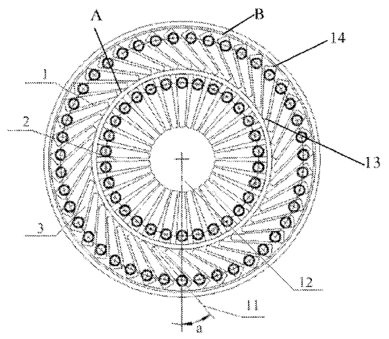
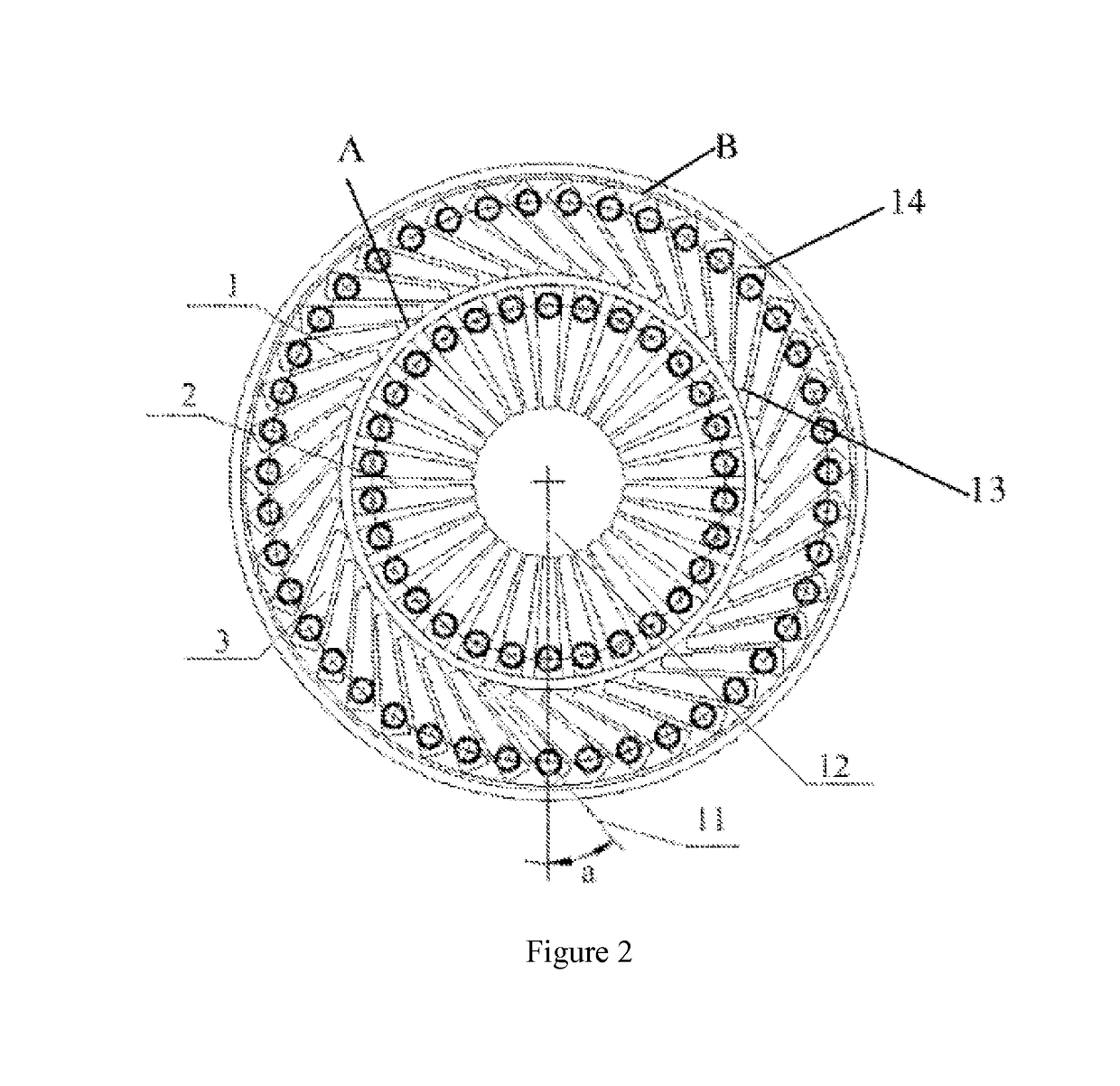
[0021]This disclosure can be suitable for various automatic analyzers, and more particularly for high-end automatic analyzers. Generally, at least two reagent wheels and at least one reaction wheel are disposed within the high-end automatic analyzer, where the two reagent wheels may be commonly arranged on the same side of the reaction wheel, and the two reagent wheels may be arranged one behind the other. Under this arrangement, reagent replacement operability for the reagent wheel located in the rear side is directly affected by a size of the reagent wheel located in the front side. In particular, when multiple modules are interconnected therewith, the automatic analyzer cannot be operated from its lateral sides, and the reagent can only be picked up or placed down from the front side of the rear side of the analyzer. Balance should thus be considered for the operabili...


PUM

PropertyMeasurementUnit
included angleaaaaaaaaaa

Abstract

This disclosure provides automatic analyzers and reagent wheels thereof. The reagent wheel can have one or more rings of reagent bottle seats that may be used for placing a reagent container and distributed along a circumferential direction. An included angle may be formed between a symmetrical centerline of the reagent container placed on the reagent bottle seat and a radius of a circle where the reagent wheel is located, where the included angle is not equal to zero. Compared with the situation in which the symmetrical centerline of the reagent container overlaps with the radius of the circle where the reagent wheel is located, an improved balance can be achieved between the capacity and the diametric size of the reagent wheel, thus making an improvement in meeting application requirements of the analyzers.

Description

TECHNICAL FIELD[0001]This disclosure generally relates to reagent wheels of automatic analyzers, and more particularly to automatic biochemical analyzers and reagent wheels thereof.BACKGROUND[0002]Automatic analyzer is a medical testing equipment commonly found in hospitals. Recently, since people have more demand for their own health condition, health examination involving various test items has been growing increasingly. This may therefore raise more demand on the automatic analyzer. For example, in a high-speed automatic biochemical analyzer, a reagent wheel may be highly demanded on its capacity, since more capacity can facilitate and support more test items, and can reduce a frequency of changing the reagent so as to enhance corresponding operation efficiency. The capacity of the reagent wheel may include an amount of a reagent seat arranged thereon and a volume of a reagent container that can be accommodated within each reagent seat. Generally, the larger the capacity of the r...

Claims


Application Information

Patent Timeline
Patent Type & Authority Patents(United States)
IPC IPC(8): G01N35/04G01N35/02B01L9/06
CPCG01N35/025B01L9/06G01N35/04B01L2300/0803G01N2035/0443G01N2035/0455
Inventor WANG, ZHIHONGLI, SHICAIZHU, XINGCAI
Owner SHENZHEN MINDRAY BIO MEDICAL ELECTRONICS CO LTD
Why Eureka
Try Eureka