
Backlight module with partially overlapped film design

a backlight module and film design technology, applied in lighting and heating apparatus, lighting device details, instruments, etc., can solve the problems of inability to completely avoid bright/dark joint marks, bad display quality, etc., to improve the transmittance improve the display quality, and increase the thickness of the overlapped area

Active Publication Date: 2017-05-23
AU OPTRONICS CORP
View PDF8 Cites 0 Cited by
  • Summary
  • Abstract
  • Description
  • Claims
  • Application Information

AI Technical Summary

Benefits of technology

The design enhances light emission through the overlapped area, reducing light loss and bright / dark joint marks, thereby improving display quality.

Problems solved by technology

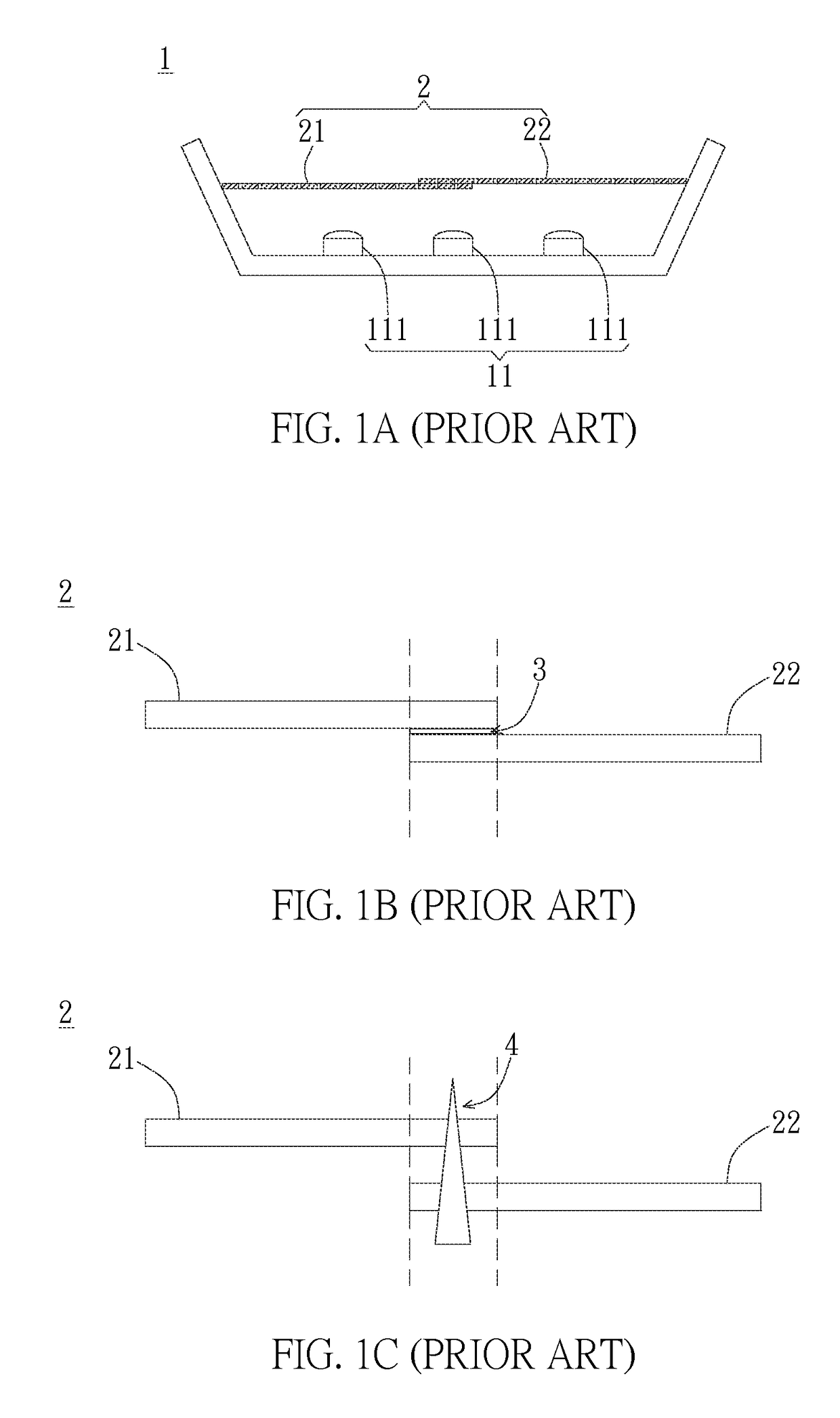
However, when designing the large size module, because of the limited length of the reflector so that the factory cannot supply one single large size reflector, it must be finished by jointing multiple reflectors.
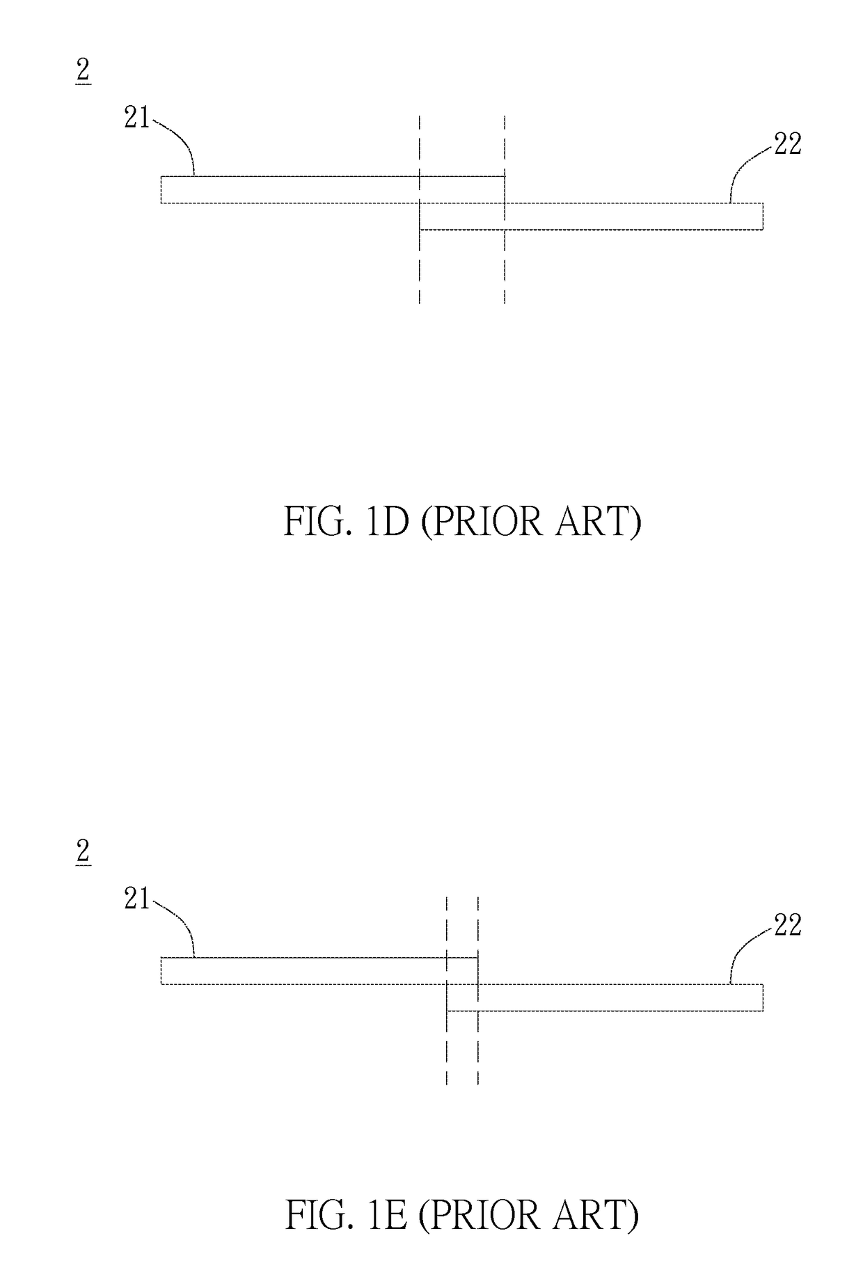
Nevertheless, the overlapped area of two reflectors could occur bright / dark joint marks and leads to bad display quality.
However, the bright / dark joint marks cannot be completely avoided.

Method used


Image

  • Backlight module with partially overlapped film design
  • Backlight module with partially overlapped film design
  • Backlight module with partially overlapped film design

Examples


Embodiment Construction

[0022]Please refer to FIG. 2A, FIG. 2A is an exploded view of a backlight module in an embodiment. A backlight module 1 preferably comprises a light source module 11 and an optical control layer 2. The light source module 11 comprises a plurality of light sources 111 (e.g. light-emitting diode, LED); furthermore, the light source module 11 preferably comprises a supporting plate 112 to support the light sources 111. The optical control layer 2 is disposed on the light source module, is configured to distribute light generated from the light sources 111 to emit through different positions. The optical control layer 2 preferably comprises multiple optical films. The multiple optical films preferably are high reflectance porous reflectors with multiple light exit openings. The light generated from light sources 111 can reflect back and forth by the optical control layer 2 and the supporting plate 112, and emit out of the optical control layer 2 from the light exit openings. Accordingly...


PUM

PropertyMeasurementUnit
diameteraaaaaaaaaa
widthaaaaaaaaaa
distanceaaaaaaaaaa

Abstract

The present invention provides a backlight module, comprising a light source module and an optical control layer disposed on the light source module. The optical control layer comprises a first optical film and a second optical film. The first optical film has a first overlap area on a first side, the first overlap area comprises first inner openings; the second optical film comprises a second overlap area near the first overlap area. The second overlap area matches the first overlap area. The second overlap area comprises second outer openings corresponding to the first inner openings.

Description

BACKGROUND OF THE INVENTION[0001]1. Field of the Invention[0002]The present invention is related a backlight module, especially a direct type backlight module with partially overlapped film.[0003]2. Description of the Prior Art[0004]FIG. 1A is a schematic diagram of a conventional direct type backlight module 1, comprising a light source module 11 and reflector 2. The light source module 11 comprises a plurality of light sources 111. The reflector 2 comprises a first reflector 21 and a second reflector 22 both disposed on the light source module 11 for distributing the light generated from the light sources 111. However, when designing the large size module, because of the limited length of the reflector so that the factory cannot supply one single large size reflector, it must be finished by jointing multiple reflectors. Nevertheless, the overlapped area of two reflectors could occur bright / dark joint marks and leads to bad display quality.[0005]The conventional way to joint multip...

Claims


Application Information

Patent Timeline
Patent Type & Authority Patents(United States)
IPC IPC(8): F21V7/22G02F1/1335
CPCG02F1/133606
Inventor CHEN, CHUNG-TINGCHUNG, WEI-CHUNWANG, MING-CHENGTSENG, SHIH-FU
Owner AU OPTRONICS CORP
Learn More