Novel arrangement of non-evaporable getters for a tube solar collector

a technology of non-evaporable getters and solar collectors, which is applied in the safety of solar heat collectors, solar heat systems, lighting and heating apparatus, etc., can solve the problems of increasing thermal losses, increasing the size or the number of getter pellets, and reducing the efficiency of the system in a significant manner

Inactive Publication Date: 2013-08-29
ABENGOA SOLAR NEW TECH SA
View PDF7 Cites 8 Cited by
  • Summary
  • Abstract
  • Description
  • Claims
  • Application Information

AI Technical Summary

Benefits of technology

[0016]1. New metal tube shape, similar to the current one, but having a glass tube with a greater diameter and a defined eccentricity with respect to the metal tube depending on the optics of the collector. The eccentricity of the tube allows improving the optical behavior of the receiver tube because the glass tube may be used as a substrate to add a solar reconcentrator by means of partial mirroring, which is discussed below.
[0023]In addition, the symmetry in the tube is maintained because both ends of the tube are identical, which supposes a thermal and manufacturing advantage due to the unification of components.
[0025]This novel arrangement also implies that if more getters are needed, the only requirement is to increase the number of pellets adhered to the cover because there is enough space, thus avoiding having to increase the diameter of the glass tube to add more pellets, with the additional advantage that the present development allows pellets of all shapes.

Problems solved by technology

These molecules end up passing through the metal tube and entering the vacuum area, increasing thermal losses and, therefore, decreasing the efficiency of the system in a significant manner.
This arrangement has the following series of inconveniences: the increase of the minimum diameter necessary to house all of these elements within, the submission of the getter to the mechanical efforts suffered by the expansion compensating bellows, the need to introduce the round getter pellets into a sheath with a protective mesh that brushes against the expansion compensating device and, if more material is needed to increase the absorption, there is no other option but to increase the size or number of getter pellets, which implies the increase of the diameter of the glass tube.
Therefore, the assembly is very artisanal and it cannot be automatized because, in addition, the pellets making up the getter are thin and very fragile.
The foregoing implies an efficiency loss because the useful surface for the capture of solar radiation is drastically reduced.

Method used


Image

  • Novel arrangement of non-evaporable getters for a tube solar collector
  • Novel arrangement of non-evaporable getters for a tube solar collector
  • Novel arrangement of non-evaporable getters for a tube solar collector

Examples


Embodiment Construction

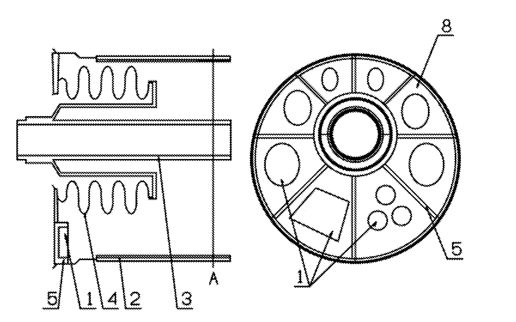
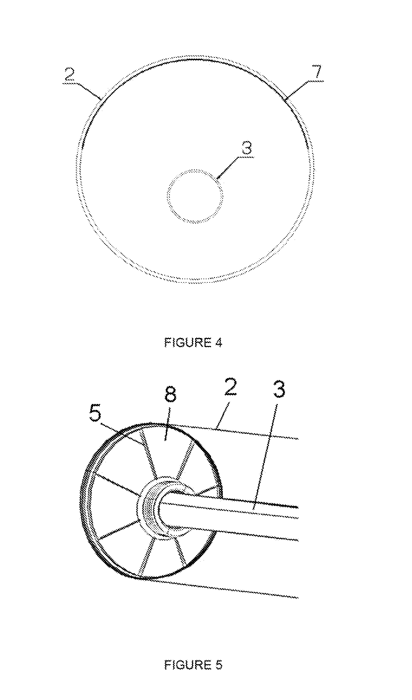
[0011]The invention consists of a new getter arrangement for a tube solar collector, as well as several modifications to the rest of the tube, mainly to its ends, according to this novel arrangement.

[0012]Despite its importance, the function of the non-evaporable getters should not interfere with the main purpose of the receiver tube, which is to maximize its thermal performance. Its arrangement should allow this situation without compromising its function to guarantee the correct aging of the product.

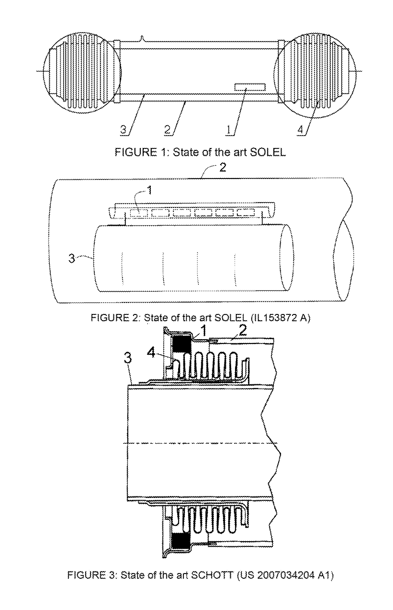
[0013]As commented above, due to its diverse locations in the state of the art, it used to originate a different casing shape in each one of the ends in order to house it, which in turn conditioned the value of the diameter of the glass or boron-silicate cylinder.

[0014]In order to solve the problems found in the known state of the art, new design proposals related to the geometry and arrangement of the tube collector and the set of non-evaporable getters have been developed.

[0015]These...


PUM


Abstract

The invention relates to a novel arrangement of non-evaporable getters for a tube solar collector, said tube collector being of the type that includes an outer glass tube (2); an inner metal tube (3) through which a heat-transfer fluid flows; a vacuum chamber between both tubes; and, at the ends, non-evaporable getter pellets (1) that absorb gas molecules that could produce a loss of vacuum between the inner tube (3) and the outer tube (2) and the covers (8) at which a bellows-type expansion compensating device (4) is positioned.The inner metal tube (3) and outer glass tube (2) are positioned eccentrically to one another, forming a thicker area and a narrower area in the cover (8), said narrower area being used for the positioning, by means of bonding, of the non-evaporable getter pellets (1).

Description

TECHNICAL SECTOR OF THE INVENTION[0001]The present invention is framed within the sector of thermosolar energy, specifically within the developments of tube solar collectors, and more specifically, it focuses on the possible location of non-evaporable getters or vacuum evacuators within this type of tube collectors.BACKGROUND OF THE INVENTION[0002]Getters are solid materials, alloys of different metals, capable of chemically absorbing gas molecules at their surface. They are broadly used for a variety of applications, such as in particle accelerators, vacuum tubes, inert gas purification systems, etc.[0003]The non-evaporable getter of the invention will be used in a vacuum tube, of those used as solar receivers. In general, these receivers consist of two concentric tubes, between which the vacuum is generated. The inner tube, through which the heated fluid flows, is metallic and the outer tube is made from glass, usually boron-silicate.[0004]A bellows-type expansion compensating dev...

Claims


Application Information

Patent Timeline
Patent Type & Authority Applications(United States)
IPC IPC(8): F24J2/05F24S10/40
CPCF24J2/055F24J2/4612Y02E10/44F24J2/465F24J2/4616F24S10/45F24S40/40F24S40/46F24S80/70Y02E10/40
Inventor NUNEZ BOOTELLO, JUAN PABLOMARTINEZ SANZ, NOELIA
Owner ABENGOA SOLAR NEW TECH SA
Why Eureka
Try Eureka