
Keypad with increased refractive index

a technology of refractive index and keypad, which is applied in the field of keys with increased refractive index, can solve the problems of poor light transmission efficiency and uniformity, low transparency of current-use rubber, and the need for four light-emitting diodes, etc., and achieve the effect of increasing the refractive index and increasing the amount of transmitted ligh

Inactive Publication Date: 2009-04-09
SILITECH TECH CORP
View PDF3 Cites 6 Cited by
  • Summary
  • Abstract
  • Description
  • Claims
  • Application Information

AI Technical Summary

Benefits of technology

[0010]The object of the present invention is to provide a keypad with increased refractive index, whereby the angle of total reflection of the light can be changed so as to increase the amount of transmitted light.
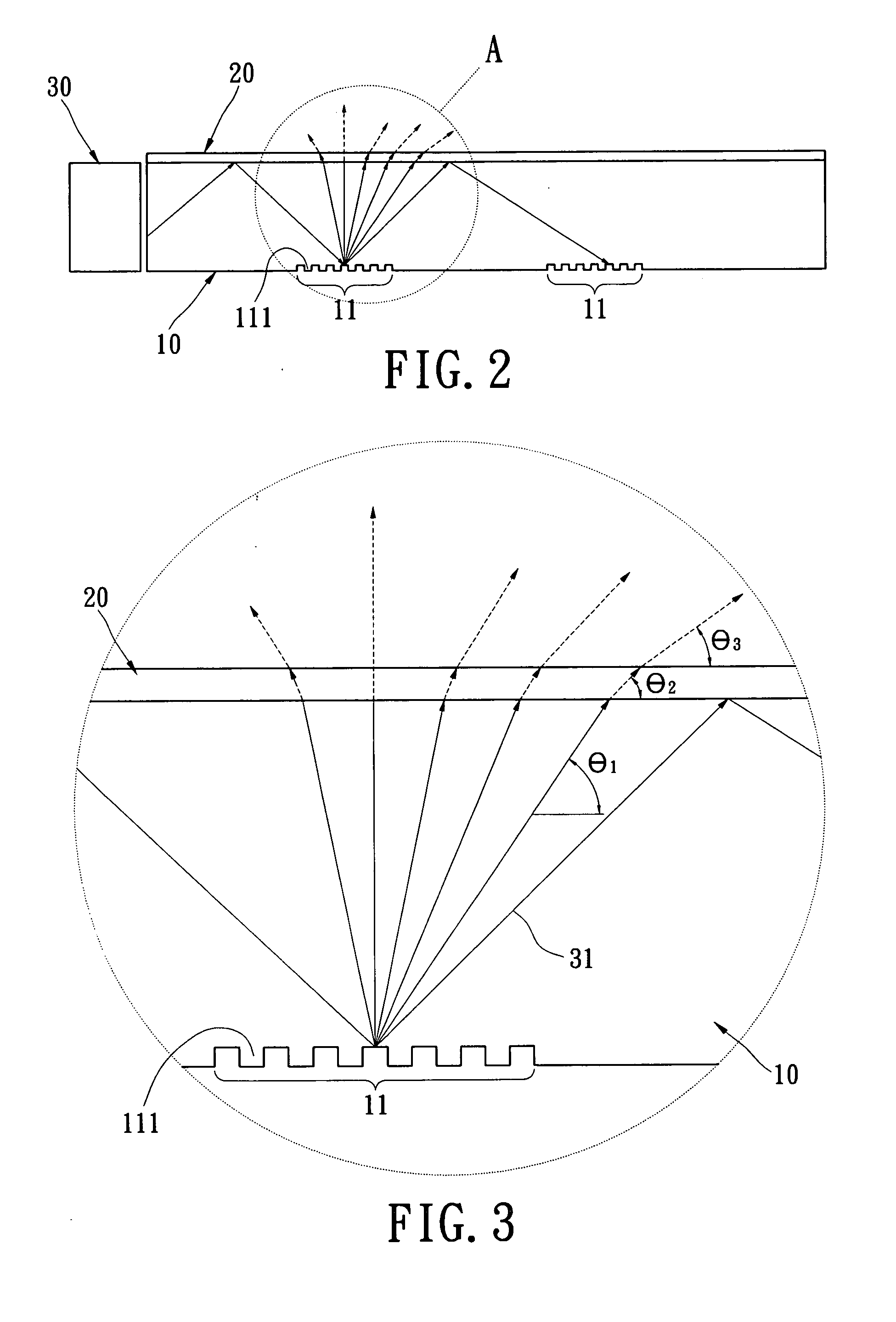
[0012]The present invention has advantageous features as follows. Since the optical refractive layer is applied on an upper surface of the light-guiding elastic element, and the refractive index of the optical refractive layer is different from that of the light-guiding elastic element. The angle of total reflection of the light in the light-guiding elastic element can be changed, causing more light to be guided outside of the light-guiding elastic element. In this way, the number of light sources used in the light-guiding elastic element can be increased. Furthermore, the luminance and uniformity of the light can be enhanced, thereby improving the optical behavior of the keypad and increasing the efficiency of the light source and a battery.

Problems solved by technology

However, the currently-used rubber has low transparency.
However, such a solution still requires four light-emitting diodes.
Therefore, in the above-mentioned solution, the efficiency of light transmission and the uniformity are poor.
Therefore, according to the above, in practice, the conventional key still has drawbacks and thus needs to be improved.

Method used


Image

  • Keypad with increased refractive index
  • Keypad with increased refractive index
  • Keypad with increased refractive index

Examples


Embodiment Construction

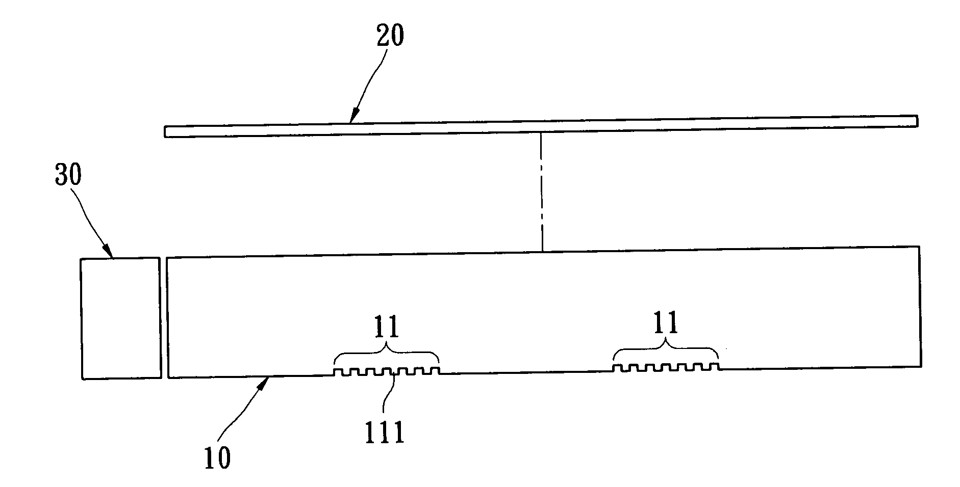
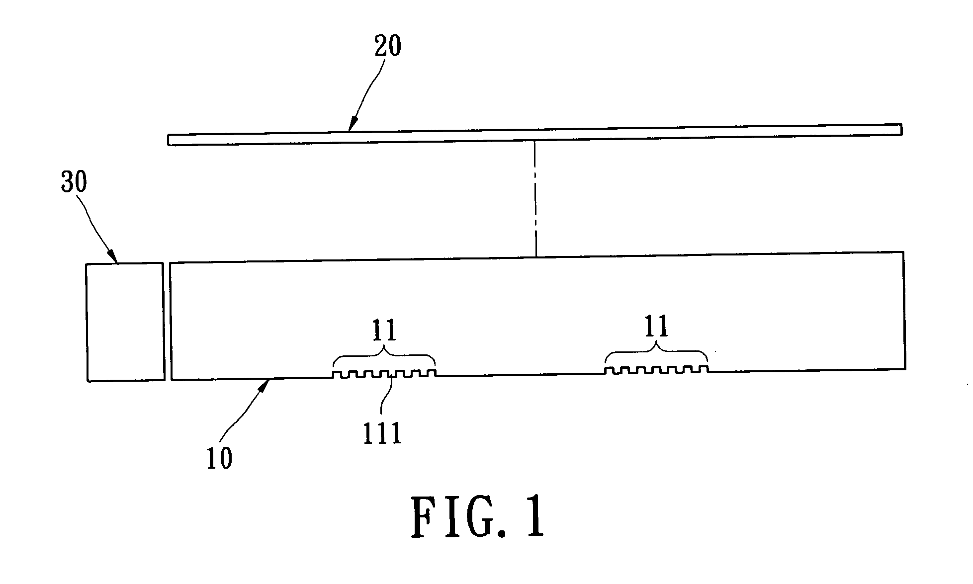
[0017]Please refer to FIGS. 1 and 2. The present invention provides a keypad with increased refractive index, which includes a light-guiding elastic element 10, an optical refractive layer 20 and at least one light-emitting element 30.

[0018]The light-guiding elastic element 10 is made of transparent rubber material or transparent plastic material. The lower surface of the light-guiding elastic element 10 is provided with a plurality of light-guiding microstructures 11. Each of the light-guiding microstructures 11 is provided with a plurality of troughs 111.

[0019]The optical refractive layer 20 is transparent and is applied on the upper surface of the light-guiding elastic element 10 by means of coating. The optical refractive layer 20 is made of materials having optical properties, such as SiO2.

[0020]The refractive index of air is defined as a real number x. The refractive index of the light-guiding elastic element 10 is defined as a real number y. The refractive index of the optica...


PUM


Abstract

A keypad with increased refractive index includes a light-guiding elastic element, an optical refractive layer and at least one light-emitting element. The optical refractive layer is applied on an upper surface of the light-guiding elastic element. The light-emitting element is provided on one side of the light-guiding elastic element. The refractive index of air is defined as a real number x. The refractive index of the light-guiding elastic element is defined as a real number y. The refractive index of the optical refractive layer is defined as a real number z. The refractive index z is larger than the refractive index x. Since the optical refractive layer is applied on the light-guiding elastic element and the refractive index of the optical refractive layer is different from that of the light-guiding elastic element, the angle of total reflection of the light in the light-guiding elastic element can be changed.

Description

BACKGROUND OF THE INVENTION[0001]1. Field of the Invention[0002]The present invention relates to a keypad, and in particular to a keypad with increased refractive index, whereby the angle of total reflection of light can be changed so as to increase the amount of transmitted light.[0003]2. Description of Related Art[0004]With the advent of the information technology era and the development of communication network technology, cell phones (also referred to as mobile phones) have become one of the most popular communication tools. Since the mobile phone is small in volume, easy to carry, and has various functions at a low price, more and more consumers like to use mobile phones. When the consumer chooses a mobile phone, the functionality and profile of the mobile phone are the chief considerations. Therefore, in order to satisfy the consumer's demands, many mobile phones have been developed with various functions and novel profiles.[0005]In order to illuminate the letters shown on the...

Claims


Application Information

Patent Timeline
Patent Type & Authority Applications(United States)
IPC IPC(8): G01D11/28
CPCG02B6/0038H04M1/22G02B6/0061
Inventor LEE, HSIN-CHIN
Owner SILITECH TECH CORP
Learn More