Optical fiber and optical communication system including the same

a technology of optical communication system and optical fiber, applied in the field of optical fiber, can solve the problems of not fully suppressing the occurrence of nonlinear optical phenomena in g652 and g654 standards, and unable to carry out optical communications over a longer distance by utilizing the conventional optical fiber

Inactive Publication Date: 2003-12-02
SUMITOMO ELECTRIC IND LTD
View PDF14 Cites 92 Cited by
  • Summary
  • Abstract
  • Description
  • Claims
  • Application Information

AI Technical Summary

Problems solved by technology

However, the optical fibers defined in G652 and G654 standards cannot fully suppress the occurrence of nonlinear optical phenomena.
Therefore, it has been difficult to carry out optical communications over a longer distance by utilizing the conventional optical fibers.
If the ratio 2b / 2a is 1.1 or less, then bending loss becomes greater, whereby the transmission quality of the optical communication system as a whole deteriorates.

Method used


Image

  • Optical fiber and optical communication system including the same
  • Optical fiber and optical communication system including the same
  • Optical fiber and optical communication system including the same

Examples


second applied example

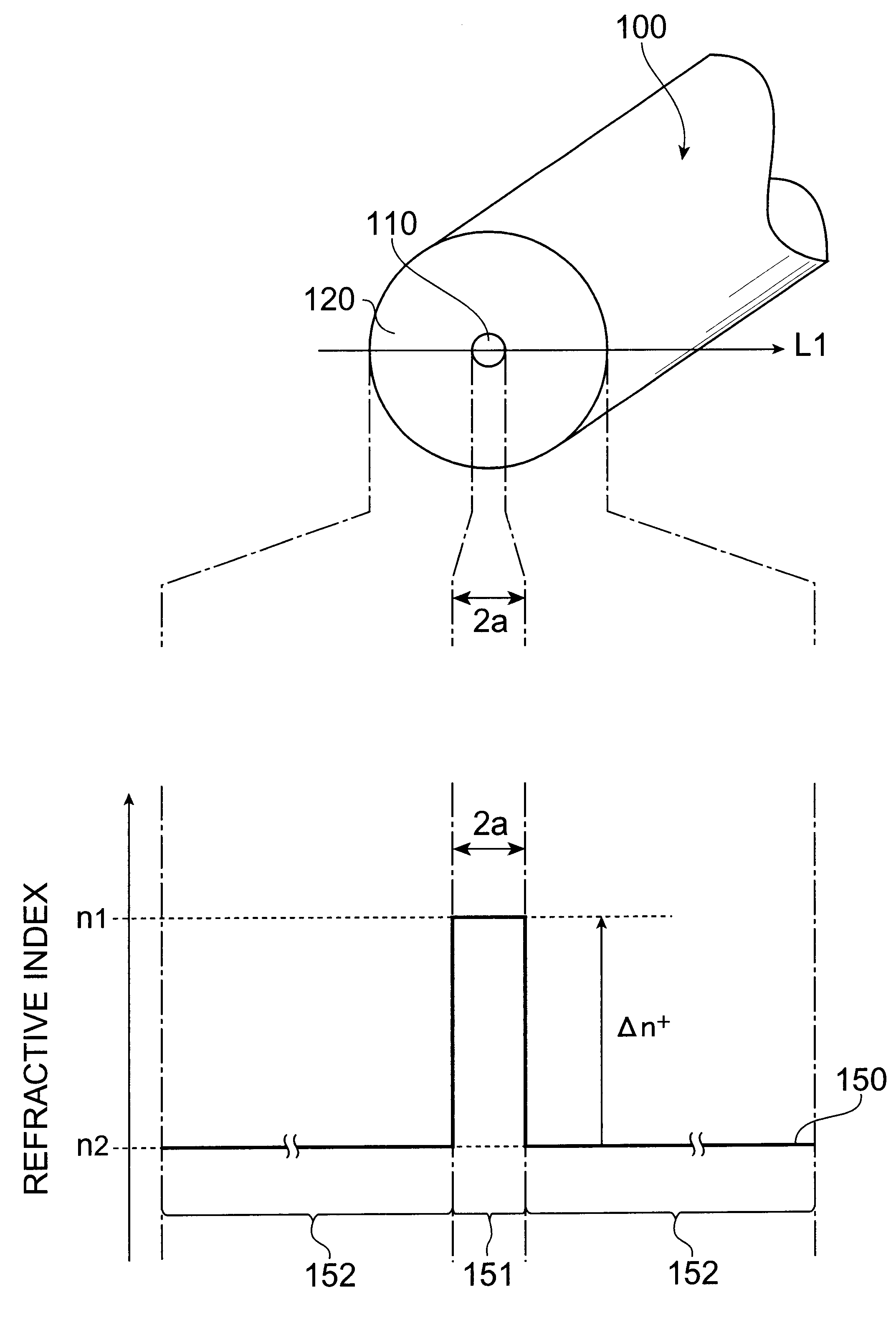
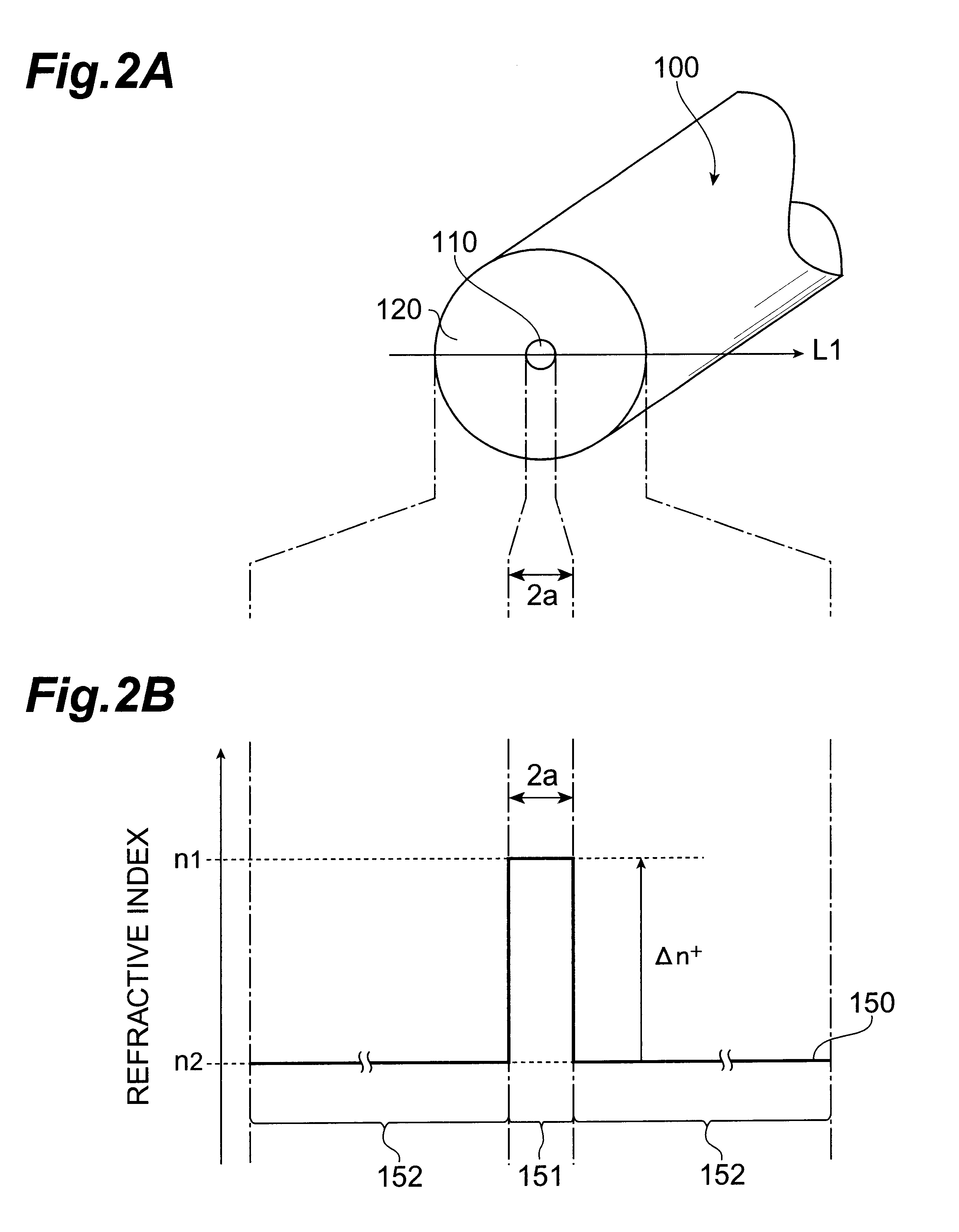
The refractive index profile of the optical fiber in accordance with the present invention may have a shape which, in its core region, changes from the center part of the core region to the outer peripheral part thereof. FIG. 12 is a view showing the refractive index profile 450 of a second applied example of the optical fiber 200 in accordance with the second embodiment, which has a shape in which the refractive index in the core region decreases from the center part to its periphery as in the above-mentioned first applied example. The second applied example also has a structure similar to the cross-sectional structure shown in FIG. 4A. Namely, as with the optical fiber 200, the optical fiber in accordance with the second applied example has a core region having an outside diameter 2a and a maximum refractive index n1 in its center part; an inner cladding having an outside diameter 2b and a refractive index n2 lower than that of the core region; and an outer cladding, made of pure ...

third applied example

A third applied example of the optical fiber 200 in accordance with the second embodiment has a depressed cladding type refractive index profile in which, contrary to that of the above-mentioned second applied example, the refractive index in the core region decreases from the periphery toward the center part. FIG. 15 is a view showing the refractive index profile 550 of the optical fiber in accordance with the third applied example, which has a structure similar to the above-mentioned cross-sectional structure shown in FIG. 4A.

Namely, as with the optical fiber 200, the optical fiber in accordance with the third applied example comprises a core region having an outside diameter 2a and a maximum refractive index n1 in its peripheral part; an inner cladding having an outside diameter 2b and a refractive index n2 lower than that of the core region; and an outer cladding, made of pure silica glass, having a refractive index n0 higher than that of the inner cladding. The core region is d...


PUM


Abstract

The present invention relates to an optical fiber having a structure suitable for long-distance optical communications, and an optical transmission line including the same. The optical fiber in accordance with the present invention comprises a core region extending along a predetermined axis, and a cladding region disposed so as to surround the outer periphery of the core region; and, as characteristics at a wavelength of 1.55 mum, an effective area of at least 110 mum<2>, a dispersion of 18 to 23 ps/nm/km, and a dispersion slope of 0.058 to 0.066 ps/nm<2>/km.

Description

1. Field of the InventionThe present invention relates to an optical fiber applicable to an optical transmission line for optical communication systems.2. Background of the InventionSingle-mode optical fibers have conventionally been used as optical transmission lines in optical communications. Such single-mode optical fibers have a zero-dispersion wavelength in the vicinity of a wavelength of 1.3 .mu.m, a positive dispersion slope in the 1.55-.mu.m wavelength band, and a dispersion of about 18 ps / nm / km at a wavelength of 1.55 .mu.m.Single-mode optical fibers having optical characteristics such as those mentioned above are defined in G652 and G654 standards of ITU-T, and have a simple refractive index profile composed of a core and a cladding. The 1.55-.mu.m wavelength band (1500 nm to 1600 nm) is applied to a signal wavelength band since silica glass, which is the main ingredient of optical fibers, has a low attenuation in this wavelength band. On the other hand, as mentioned above...

Claims


Application Information

Patent Timeline
Patent Type & Authority Patents(United States)
IPC IPC(8): G02B6/036G02B6/02
CPCG02B6/02019G02B6/02257G02B6/0228H04B10/25253G02B6/03611G02B6/03627G02B6/0281
Inventor HIRANO, MASAAKIKATO, TAKATOSHI
Owner SUMITOMO ELECTRIC IND LTD
Why Eureka
Try Eureka