
Retaining assembly

a technology of assembly and brake device, which is applied in the direction of braking system, furniture parts, braking components, etc., can solve the problems of considerable complexity in fitting and removing the brake device again, and achieve the effect of simple and rapid assembly of the brake device and the least possible structural and functional complexity

Active Publication Date: 2017-05-30
CONTINENTAL TEVES AG & CO OHG
View PDF11 Cites 0 Cited by
  • Summary
  • Abstract
  • Description
  • Claims
  • Application Information

AI Technical Summary

Benefits of technology

[0004]An aspect of the invention improves a retaining subassembly of the type set out in such a manner that, with the least possible structural and functional complexity, particularly simple and rapid assembly of the brake device on the bulkhead is ensured, wherein the supply, orientation and securing of the brake device is intended to be carried out using simple means exclusively at the side of the bulkhead facing the engine compartment.

Problems solved by technology

The complexity for fitting and removing the brake device again is consequently considerable as a result of the poor accessibility of the bulkhead in the vehicle inner space.

Method used


Image

  • Retaining assembly
  • Retaining assembly
  • Retaining assembly

Examples


Embodiment Construction

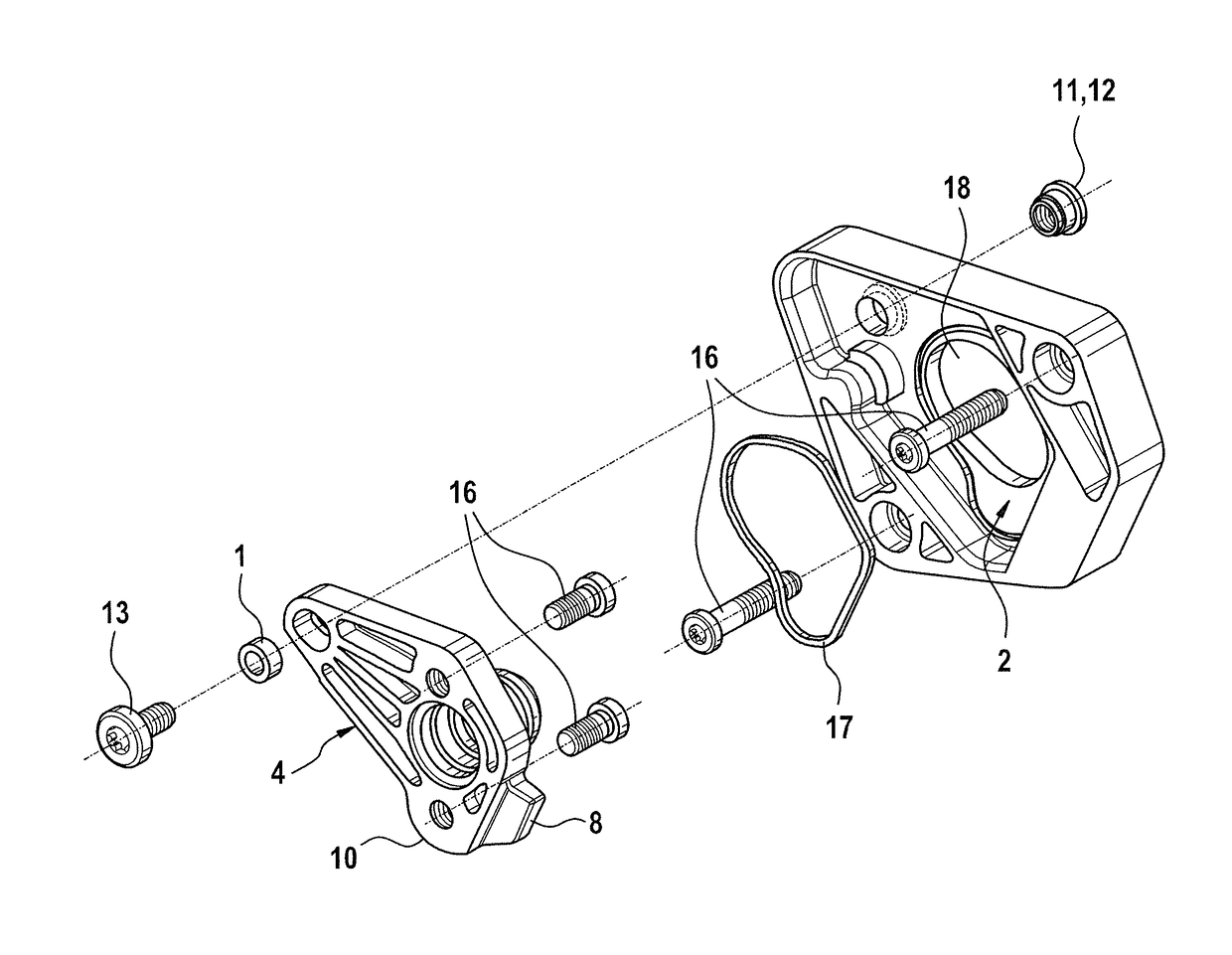
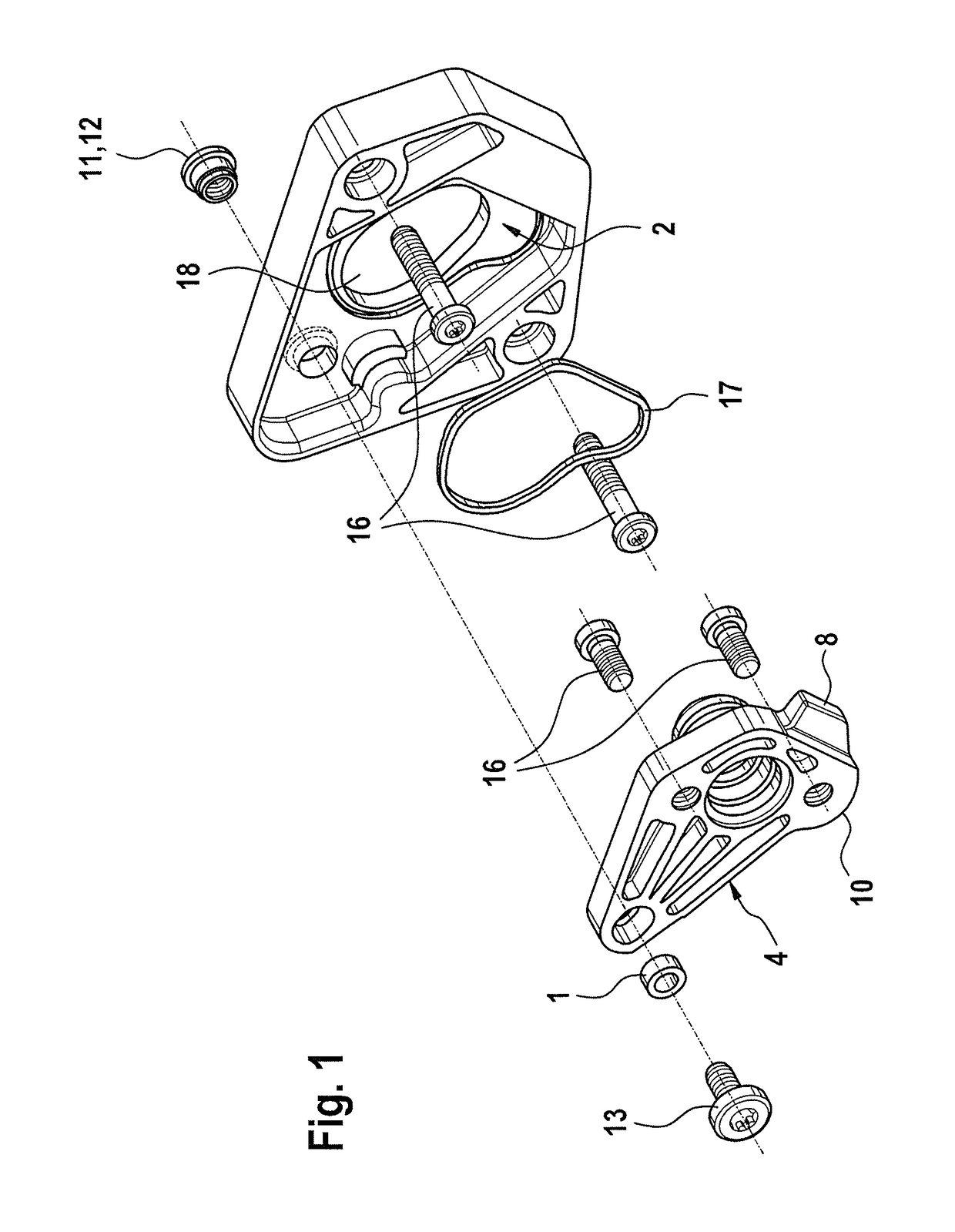
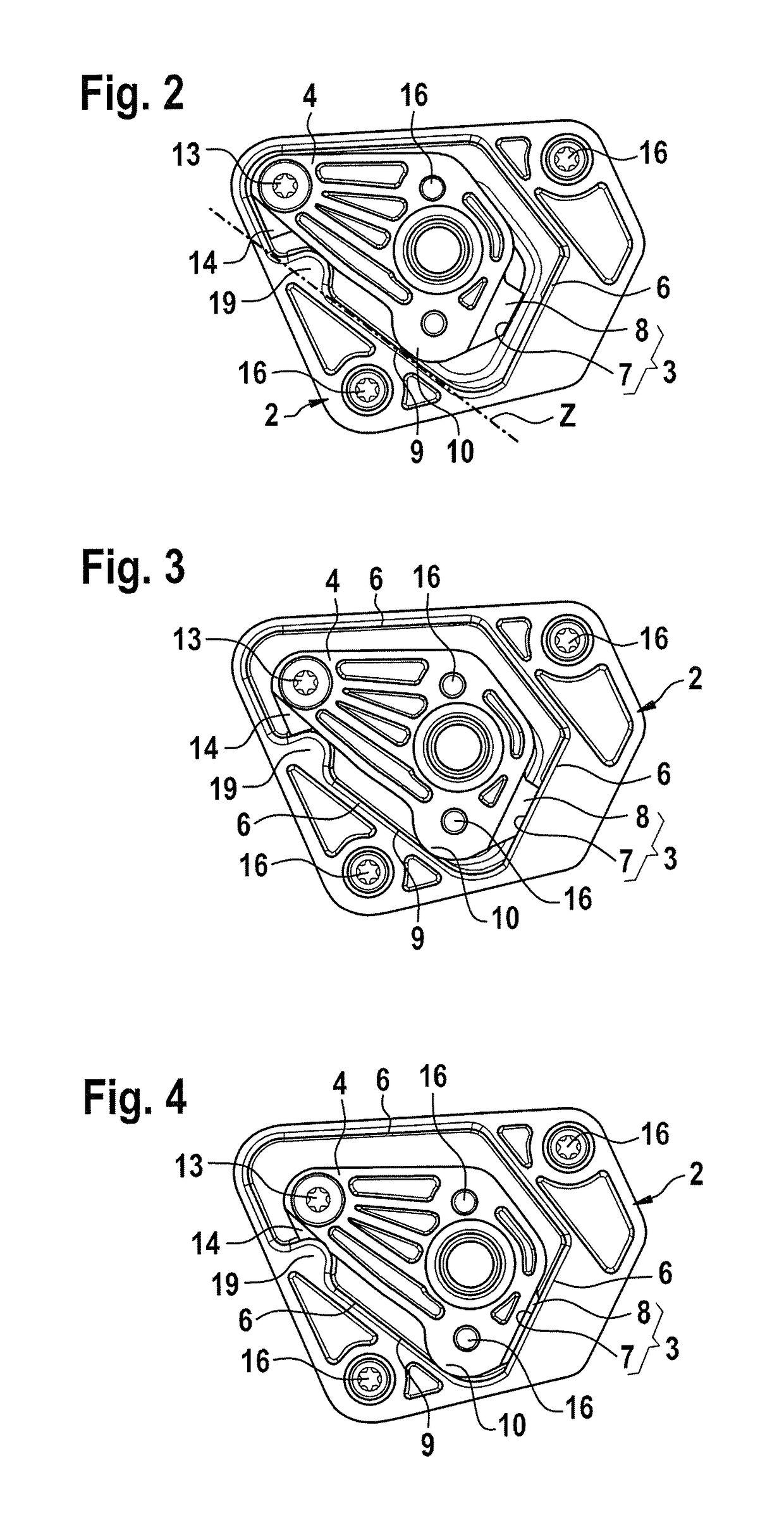
[0009]FIG. 1 is a perspective view of the significant details of a retaining subassembly for fixing a flange portion 4 which is secured to a brake device to a retention plate 2 which is securely screwed to a bulkhead (not illustrated) of a motor vehicle and which separates an engine compartment from a vehicle inner space. The retention plate 2 and the flange portion 4 are coupled to each other by means of a positive-locking connection 3, which is explained below with reference to FIGS. 2 to 5.

[0010]FIG. 1 first shows the flange portion 4 which is intended to be secured by means of two screws 16 to the brake device which is not illustrated and the securing of the retention plate 2 to the bulkhead which is not illustrated by means of two retention screws 16, for which reason there is generally arranged inside the vehicle inner space on the bulkhead a pedal block, in which the two retention screws 16 after being introduced into the two through-holes of the retention plate 2 are screwed...


PUM


Abstract

A retaining assembly for fixing a flange part, which is provided on a braking device, to a firewall of a motor vehicle, the firewall separating an engine chamber from a vehicle interior. A retaining plate is secured to the firewall face facing the engine chamber, and the flange part and the retaining plate are engaged with each other by both a form-fitting as well as force-fitting connection.

Description

CROSS REFERENCE TO RELATED APPLICATIONS[0001]This application is the U.S. National Phase Application of PCT International Application No. PCT / EP2014 / 069480, filed Sep. 12, 2014, which claims priority to German Patent Application No. 10 2013 220 573.2, filed Oct. 11, 2013 and German Patent Application No. 10 2014 201 704.1, filed Jan. 31, 2014, the contents of such applications being incorporated by reference herein.FIELD OF THE INVENTION[0002]The invention relates to a retaining subassembly for fixing a flange portion which is provided on a brake device to a bulkhead of a motor vehicle.BACKGROUND OF THE INVENTION[0003]A retaining subassembly for fixing a flange portion which is provided on a brake device to a bulkhead of a motor vehicle which separates an engine compartment from a vehicle inner space is known, for example, from DE 44 03 466 A1 which is incorporated by reference. The retaining subassembly has two stay bolts which are introduced from the flange portion of the brake de...

Claims


Application Information

Patent Timeline
Patent Type & Authority Patents(United States)
IPC IPC(8): A47B96/06B60T11/16B60T17/04
CPCB60T11/16B60T17/046B60T7/045
Inventor TARANDEK, KRISTIJANSELLINGER, THOMASDROTT, PETERGORLACH, JOHANNESKRAMER, HORST
Owner CONTINENTAL TEVES AG & CO OHG
Learn More