
Rotor for a disintegration device

a technology of disintegration device and rotor, which is applied in the direction of grain treatment, etc., can solve the problems of only realizing the fit and costly assembly/disassembly of the rotor disk

Active Publication Date: 2020-09-29
KHD HUMBOLDT WEDAG GMBH
View PDF16 Cites 0 Cited by
  • Summary
  • Abstract
  • Description
  • Claims
  • Application Information

AI Technical Summary

Benefits of technology

The invention provides a rotor for a device for disintegrating feedstock, which reduces the risk of the rotor disks deflecting and creeping out sideways. The rotor disks are connected to the retaining flanges by screws, which ensures a secure and play-free connection. The rotor disks and retaining flanges are designed with recesses and webs that fit together to form common recesses, which facilitate assembly and disassembly. The rotor disk is pushed-on in the axial direction over the drive shaft and then rotated to position the recesses and webs in their proper locations. This reduces the risk of friction during assembly and ensures a stable connection.

Problems solved by technology

An interference fit is only to be realized in exceptional cases of particularly large forces and torques; the disadvantage of the press fit thereof, in particular, is a costly assembly / disassembly of the rotor disks.

Method used


Image

  • Rotor for a disintegration device
  • Rotor for a disintegration device
  • Rotor for a disintegration device

Examples


Embodiment Construction

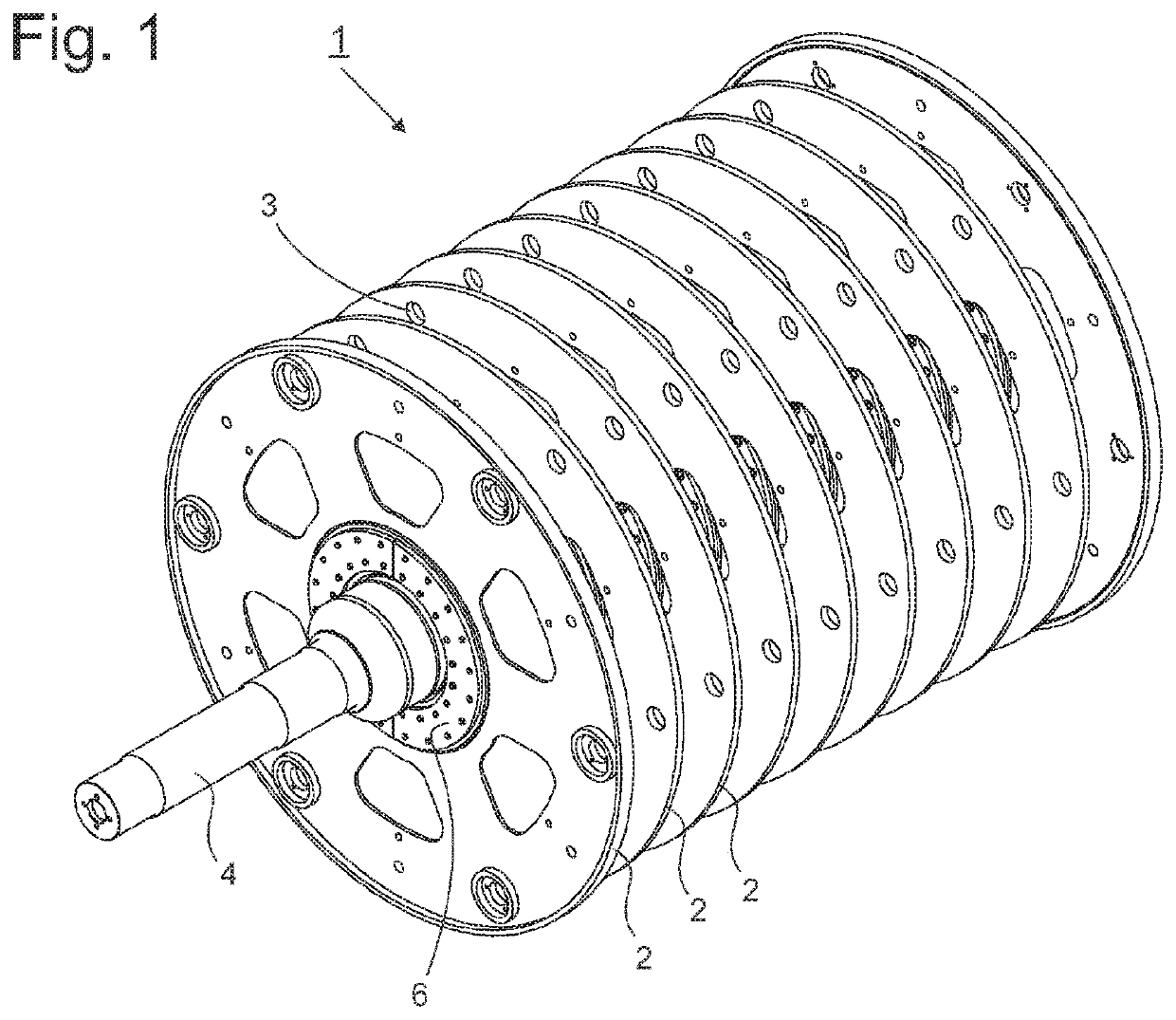
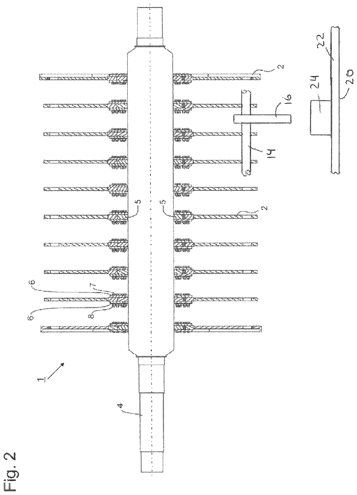
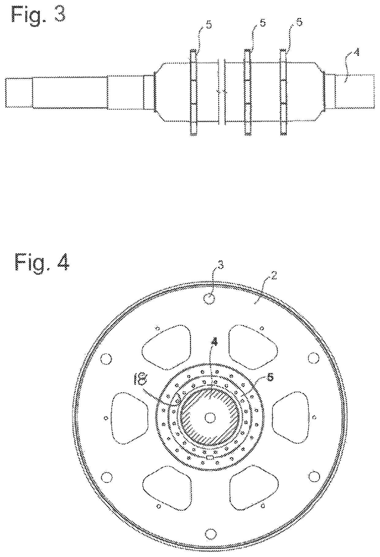
[0023]FIG. 1 shows a rotor 1 according to the invention for a device for disintegrating feedstock, for instance for an impact hammer mill used in the production of cement. The disintegration tools are not shown. However, it is possible to see axial holes 3, which are arranged in the outer region of the rotor disks 2 and are provided for the axial rods 14 (FIG. 2) on which pivotable disintegration tools 16, in particular hammers, are arranged in the region between the rotor disks 2. When the rotor 1 is rotated, the hammers 16 pivot following the centrifugal force into a position directed radially outward, in which they project beyond the outer disk edge and act in a disintegrating manner on particles of the feedstock. The rotor disks 2 are arranged on a drive shaft 4. Each rotor disk 2, in this case, is arranged on a circular ring-shaped retaining flange 5. The rotor disk 2, in this case, comprises a circular hub bore 18 for the connection to the retaining flange 5.

[0024]FIG. 3 shows...


PUM


Abstract

A rotor for a device for disintegrating feed material, comprising a drive shaft, a plurality of rotor disks mounted on the drive shaft, and disintegration tools arranged in the region of the outer circumference of the rotor disks. A holding flange is provided for each rotor disk for connecting the rotor disk to the drive shaft, wherein the holding flange is permanently connected to the drive shaft and detachably connected to the rotor disk. Devices for disintegrating feed material, in particular impact hammer mills, may thus be operated with a rotor, in which the risk of a shaking out and a lateral wandering of the rotor disks is largely eliminated.

Description

CROSS-REFERENCES TO RELATED APPLICATIONS[0001]This application claims the benefit of the German patent application No. 10 2015 012 588.5 filed on Sep. 29, 2015, the entire disclosures of which are incorporated herein by way of reference.BACKGROUND OF THE INVENTION[0002]The invention relates to a rotor for a device for disintegrating feedstock, comprising a drive shaft, a plurality of rotor disks which sit on the drive shaft and disintegration tools which are arranged in the region of the outer circumference of the rotor disks; the invention additionally relates to a device for disintegrating feedstock.[0003]Rotors are used in devices for disintegrating feedstock for the coarse or fine disintegration or deagglomeration of the feedstock as a result of beating forces, shear forces or impact forces. Disintegration tools such as blades, hammers or beating bars are arranged for this purpose in the outer circumferential region of the rotor disks, which are arranged as hubs on at least one ...

Claims


Application Information

Patent Timeline
Patent Type & Authority Patents(United States)
IPC IPC(8): B02C13/04B02C13/16B02C13/26B02C13/28
CPCB02C13/16B02C13/04B02C13/26B02C2013/2808
Inventor LOMPA, DIETERKIRCHMANN, RAINER
Owner KHD HUMBOLDT WEDAG GMBH
Learn More