Bearing unit for a turbocharger rotor

a technology for bearing units and turbochargers, which is applied in the direction of sliding contact bearings, mechanical equipment, machines/engines, etc., can solve the problems of high accuracy, increased installation space, and parts that have to be mounted

Active Publication Date: 2020-07-23
BORGWARNER INC
View PDF0 Cites 0 Cited by
  • Summary
  • Abstract
  • Description
  • Claims
  • Application Information

AI Technical Summary

Benefits of technology

[0011]In refinements which can be combined with all refinements which have been described up to now, moreover, the projection can serve for axially securing the bearing bush. The projection for axially securing the bearing bush can interact with a housing cover or a torque-proof component of an axial bearing of the turbocharger rotor. An axially extending pin can be arranged on the housing cover or the torque-proof component of the axial bearing, which pin interacts with the projection for axially securing the bearing bush. As an alternative, an axially extending pin can be arranged in the region of a radial end of the projection, which pin interacts with the housing cover or the torque-proof component of the axial bearing for axially securing the bearing bush. The bearing arrangement according to the invention therefore not only has the advantage that the projection of the bearing bush serves as an anti-rotation safeguard for the bearing bush, but rather also that the projection at the same time serves as a means for axially securing the bearing bush in the bearing housing. The axially extending pin on the torque-proof component of the axial bearing or the housing cover or the projection ensures that a certain spacing is guaranteed in the axial direction between the bearing bush and the rotating components of the axial bearing, and no contact occurs between the bearing bush and the rotating components of the axial bearing.

Problems solved by technology

In addition to the disadvantage that additional parts have to be mounted, all of these solutions require, owing to the system, high accuracy during the production and / or increased installation space.
The additional parts increase the complexity of the bearing unit, the susceptibility to faults during assembly, and the costs for the bearing unit.
The increased installation space requirement necessitates a greater overhang of the compressor impeller in relation to the radial mounting of the rotor, which has a disadvantageous effect on the dynamics of the rotor (rotor dynamics).

Method used


Image

  • Bearing unit for a turbocharger rotor
  • Bearing unit for a turbocharger rotor
  • Bearing unit for a turbocharger rotor

Examples


Embodiment Construction

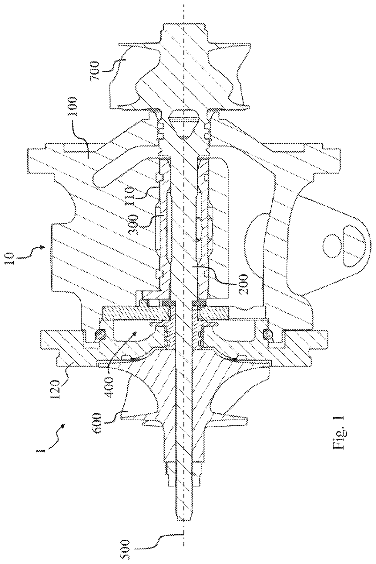
[0021]In the following text, exemplary embodiments for the bearing unit 10 according to the invention will be described using the figures. Within the context of this application, radial faces / side faces relate to faces which lie in planes which are arranged orthogonally with respect to the longitudinal axis / rotational axis 500 of the turbocharger rotor 200.

[0022]FIG. 1 shows a part of a supercharging apparatus 1 having a bearing unit 10 according to the invention. In addition to the bearing unit 10, the supercharging apparatus 1 has a compressor impeller 600 and a turbine wheel 700 which are mounted rotatably on the common turbocharger rotor 200 in the bearing unit 10. Corresponding compressor and turbine housings are omitted in FIG. 1. During operation of the supercharging apparatus 1, the turbine wheel 700 is driven by the exhaust gas stream from the internal combustion engine, as a result of which the compressor impeller 600 is also set in rotation. The compressor impeller 600 in...


PUM


Abstract

The invention relates to a bearing unit for a turbocharger rotor. The bearing unit comprises a bearing housing and a bearing bush which is arranged in a central bore for radially mounting a turbocharger rotor in the bearing housing. In the region of a first axial end, the bearing bush has a radially outwardly extending projection. The projection is designed to interact with the bearing housing as an anti-rotation safeguard for the bearing bush.

Description

FIELD OF THE INVENTION[0001]The present invention relates to a bearing unit for a turbocharger rotor, and to a supercharging apparatus having a corresponding bearing unit.BACKGROUND OF THE INVENTION[0002]Vehicles of the newer generation are increasingly being equipped with supercharging apparatuses, in order to achieve the requirement targets and legal requirements. In the case of the development of supercharging apparatuses, the aim is to optimize both the individual components and the system as an entirety with regard to their reliability and efficiency.[0003]For example, exhaust gas turbochargers are known, in the case of which a turbine is driven by the exhaust gas stream of the internal combustion engine by way of a turbine wheel. A compressor impeller which is arranged on a common rotor with the turbine wheel compresses the fresh air which is sucked in for the engine. As a result, the air or oxygen quantity which is available to the engine for combustion is increased, which in...

Claims


Application Information

Patent Timeline
Patent Type & Authority Applications(United States)
IPC IPC(8): F16C17/18F16C17/02F01D25/16
CPCF16C17/18F01D25/16F16C17/02F01D25/28F05D2220/40F16C2226/76F16C2360/24F16C2226/50F16C27/02Y02T10/12
Inventor KOENIG, LOTHARSCHUMNIG, OLIVER
Owner BORGWARNER INC
Why Eureka
Try Eureka