
Integrated phantom-powered JFET circuit module in portable electronic device for creating hi-fidelity sound characteristics

a technology of portable electronic devices and circuit modules, which is applied in the direction of low frequency amplifiers, transducer types, microphone structural associations, etc., can solve the problems of poor signal-to-noise ratio and nonlinear recording characteristics of conventionally integrated preamplifiers or amplifiers in consumer electronic devices, and the post-preamplifier stage correction is difficult and exacerbating any problems from the preamplifier

Active Publication Date: 2017-05-30
CLOUD RODGER
View PDF6 Cites 4 Cited by
  • Summary
  • Abstract
  • Description
  • Claims
  • Application Information

AI Technical Summary

Benefits of technology

The present invention provides a phantom-powered JFET preamplifier gain circuit for a microphone, which uses phantom power to amplify the microphone signal. This circuit has improved linearity and reduced noise, resulting in better sound quality. Additionally, it provides an electronic device incorporating this gain circuit, which can be powered by an external power supply or a simulated phantom power. The technical effects of the invention include improved sound quality and reduced noise in microphone recordings, as well as improved performance in electronic devices incorporating the phantom-powered JFET gain circuit.

Problems solved by technology

For example, an undesirable introduction of distortions or noise at or before the preamplifier stage may be magnified by subsequent amplification stages, thereby making post-preamplifier stage correction difficult and exacerbating any problems from the preamplifier to recording equipment or a listener.
Unfortunately, many consumer electronic devices today do not provide a professional-level hi-fidelity and linear recording characteristics for audio recording.
Conventionally-integrated preamplifiers or amplifiers in consumer electronic devices often suffer from a poor signal-to-noise ratio and nonlinear recording characteristics.
Unwanted distortions, noise, and / or nonlinear transformations of sound at an early amplification stage in the consumer electronic devices result in reduced recorded sound quality.

Method used


Image

  • Integrated phantom-powered JFET circuit module in portable electronic device for creating hi-fidelity sound characteristics
  • Integrated phantom-powered JFET circuit module in portable electronic device for creating hi-fidelity sound characteristics
  • Integrated phantom-powered JFET circuit module in portable electronic device for creating hi-fidelity sound characteristics

Examples


Embodiment Construction

[0027]Specific embodiments of the invention will now be described in detail with reference to the accompanying figures. Like elements in the various figures are denoted by like reference numerals for consistency.

[0028]In the following detailed description of embodiments of the invention, numerous specific details are set forth in order to provide a more thorough understanding of the invention. However, it will be apparent to one of ordinary skill in the art that the invention may be practiced without these specific details. In other instances, well-known features have not been described in detail to avoid unnecessarily complicating the description.

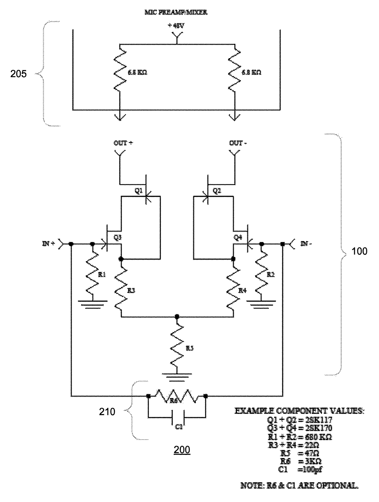
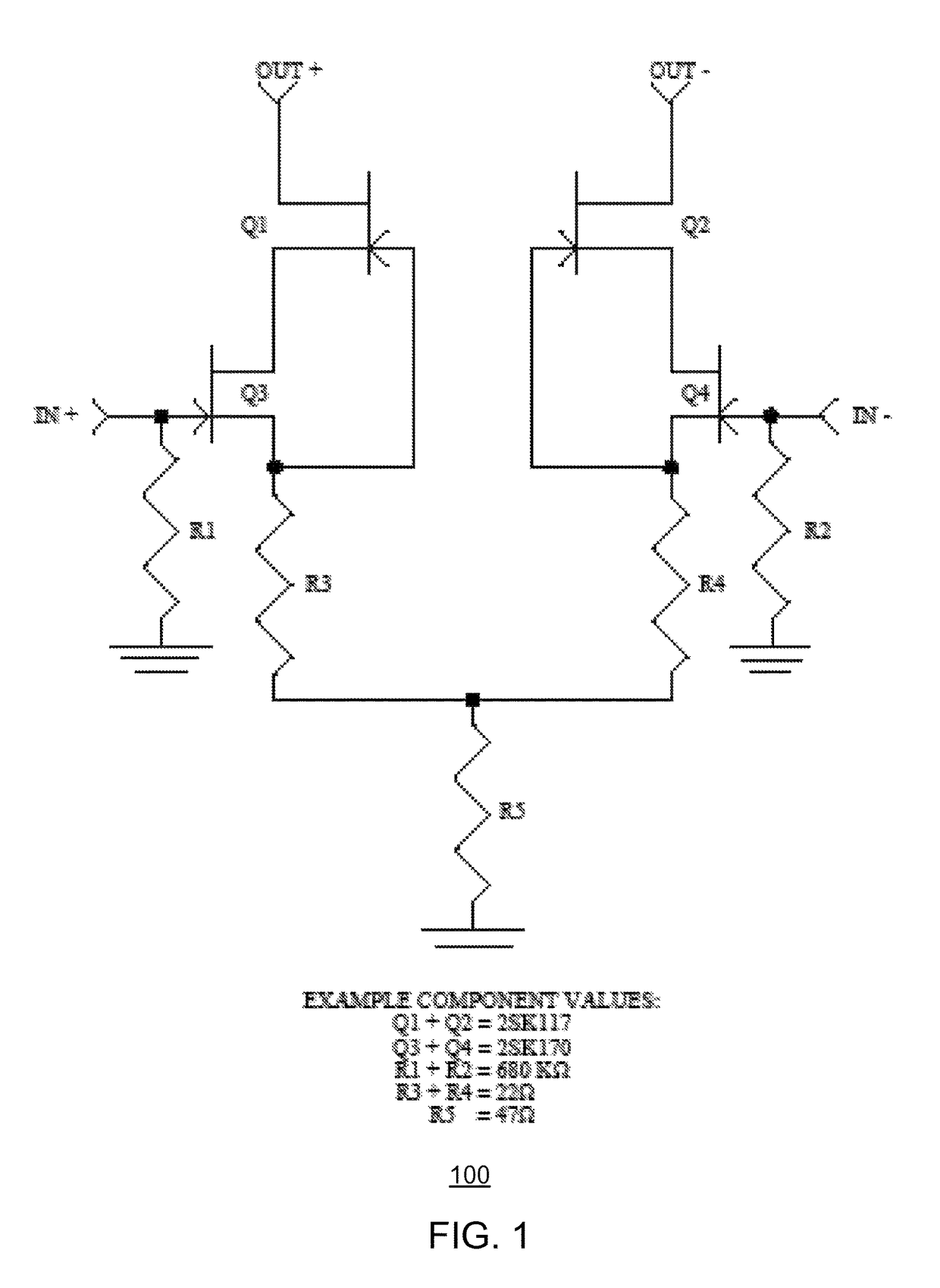
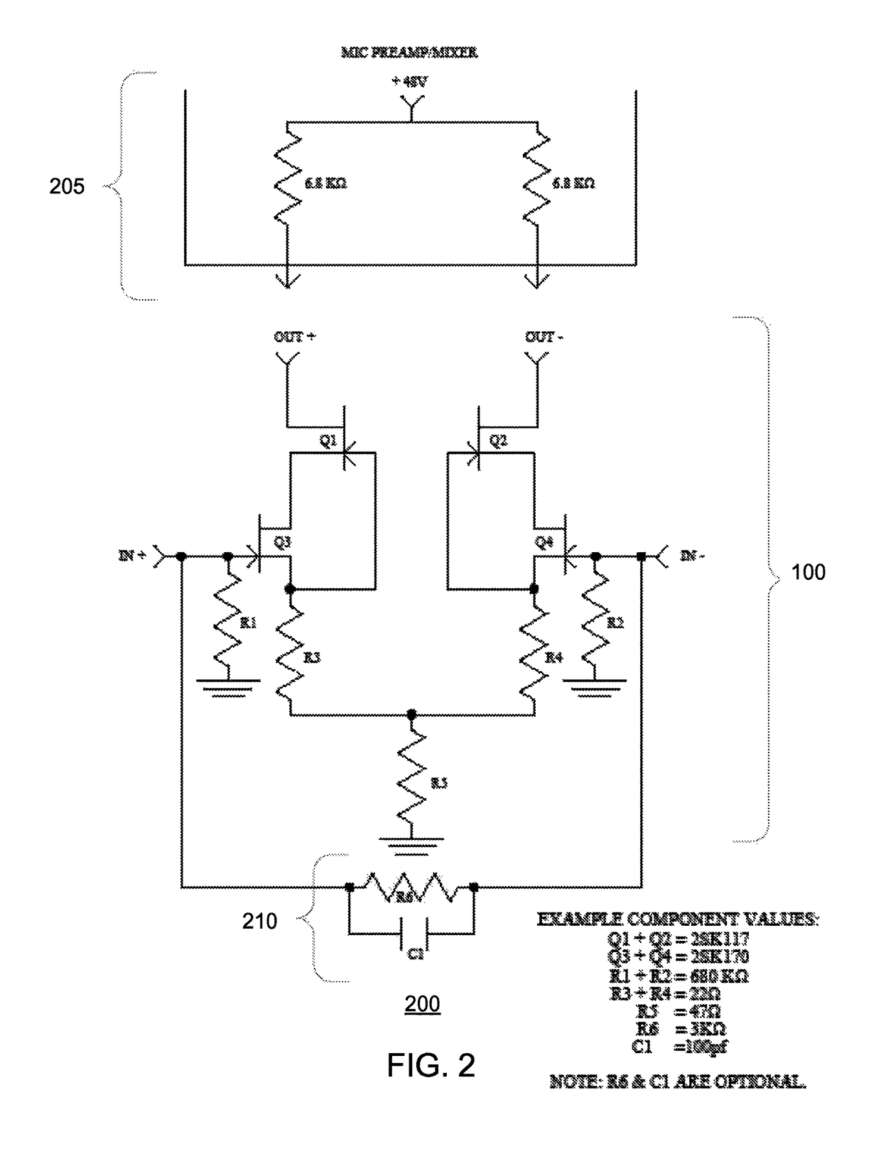
[0029]The detailed description is presented largely in terms of description of shapes, configurations, and / or other symbolic representations that directly or indirectly resemble a phantom-powered JFET circuit, which may be incorporated in a standalone preamplifier unit or integrated into various consumer electronic devices that include or ...


PUM


Abstract

A novel phantom-powered JFET gain circuit that improves audio clarity and linearity, while reducing a high-gain burden, noise, and distortion from a sole usage of a conventional preamplifier, is disclosed. In one embodiment, the novel phantom-powered JFET gain circuit is encased as a standalone box that connects to a microphone on one end and a conventional preamplifier unit or another conventional audio processing unit on another end. In another embodiment, the novel phantom-powered JFET gain circuit is integrated into a portable electronic device or another consumer electronic device with a microphone to provide an earliest-stage gain in a microphone-captured audio signal processing pathway. Yet in another embodiment, the novel phantom-powered JFET gain circuit is integrated into a preamplifier unit and provides the earliest-stage gain in a microphone-captured audio signal processing pathway, prior to additional and conventional signal amplification by the preamplifier unit.

Description

INCORPORATION BY REFERENCE[0001]The present application incorporates U.S. Ser. No. 13 / 854,839 by reference. Furthermore, the present application is a continuation-in-part application of an earlier-filed US divisional application, U.S. Ser. No. 13 / 854,839, which was filed on Apr. 1, 2013, with the earliest priority date of Oct. 9, 2009 from a U.S. provisional application, 61 / 250,001.[0002]In addition, the present application also incorporates U.S. Ser. No. 13 / 655,840 by reference. Moreover, the present application is also a continuation-in-part application of an earlier-filed US non-provisional application, U.S. Ser. No. 13 / 655,840, which was filed on Oct. 19, 2012.[0003]Furthermore, the present application also incorporates U.S. Ser. No. 14 / 158,863 by reference. The present application is also a continuation-in-part application of an earlier-filed US non-provisional application, U.S. Ser. No. 14 / 158,863, which was filed on Jan. 19, 2014.BACKGROUND OF THE INVENTION[0004]Audio preampl...

Claims


Application Information

Patent Timeline
Patent Type & Authority Patents(United States)
IPC IPC(8): H04R3/00H03F1/02H03F3/185
CPCH04R3/00H03F1/0211H03F3/185H03F2200/03H04R2420/09H03F3/45188H03F2203/45576H03F2203/45591H03F2203/45604H04R1/04H04R19/016H04R2430/01
Inventor CLOUD, RODGER
Owner CLOUD RODGER
Learn More