Device and method for safe location and marking of a biopsy cavity

a technology for sendinginel nodes and biopsy cavities, applied in medical preparations, medical science, diagnostics, etc., can solve the problems of hemostatic material and sponge configuration, and achieve the effect of low-invasive, high-intensity ultraviolet techniques

Inactive Publication Date: 2017-06-06
DEVICOR MEDICAL PROD
View PDF318 Cites 13 Cited by
  • Summary
  • Abstract
  • Description
  • Claims
  • Application Information

AI Technical Summary

Benefits of technology

[0032]The marking device may additionally contain a variety of drugs, such as hemostatic agents, pain-killing substances, or even healing or therapeutic agents that may be delivered directly to the biopsy cavity. Furthermore, the material and configuration of the sponge itself may be hemostatic. Importantly, the device is capable of accurately marking a specific location, such as the center, of the biopsy cavity, and providing other information about the patient or the particular biopsy or device deployed.
[0053]Another example of a detectable agent is a biologically compatible magnetically detectable body such as a magnetic microsphere. Such a magnetically detectable body can be the echogenic microsphere described above that is either fabricated from or coated with a magnetic material. Alternatively, the magnetically detectable body may be a solid or other type of magnetic body capable of being incorporated into a carrier fluid and deposited around the lesion or its cavity as described above. These bodies are preferably capable of migration to and accumulation in the SN so that, in a similar fashion to the echogenic microspheres, the cumulative magnetic field produced by these magnetic bodies allows for location of the SN by remote and noninvasive means.

Problems solved by technology

Furthermore, the material and configuration of the sponge itself may be hemostatic.

Method used


Image

  • Device and method for safe location and marking of a biopsy cavity
  • Device and method for safe location and marking of a biopsy cavity
  • Device and method for safe location and marking of a biopsy cavity

Examples


Embodiment Construction

[0089]The following illustrations are examples of the invention described herein. It is contemplated that combinations of aspects of specific embodiments or combinations of the specific embodiments themselves are within the scope of this disclosure.

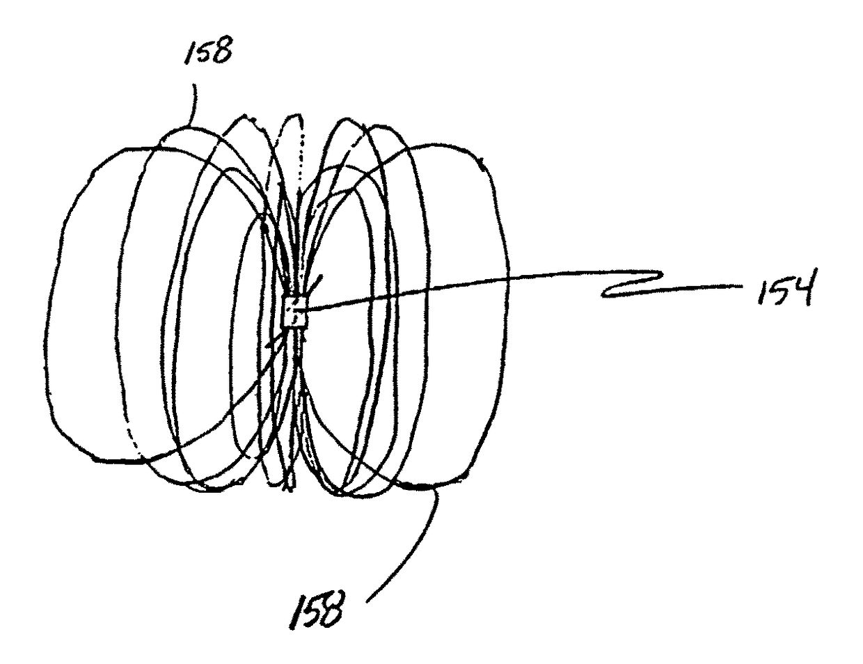
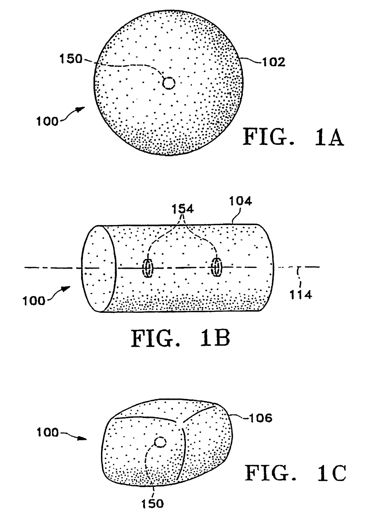
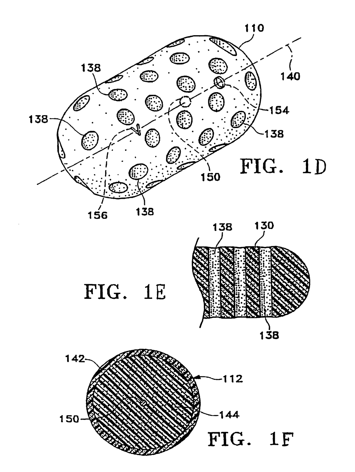
[0090]FIGS. 1A-1M show various configurations of a preferred subcutaneous cavity marking device of the present invention. Here the marking device 100 is displayed as having either a generally spherical body 102 (FIG. 1A), a generally cylindrical body 104 (FIG. 1B), or a multi-faced or irregular body 106 (FIG. 1C). In general, it is within the scope of this invention for the body to assume a variety of shapes. For example, the body may be constructed to have substantially curved surfaces, such as the preferred spherical 102 and cylindrical 104 bodies of FIGS. 1A and 1B, respectively. The body may have conical or ellipsoidal, etc. shapes as well. It is further within the scope of this invention for the body to have substantially planar surf...


PUM


Abstract

Cavity and sentinel lymph node marking devices, marker delivery devices, and methods are disclosed. More particularly, upon insertion into a body, the cavity marking device and method enable one to determine the center, orientation, and periphery of the cavity by radiographic, mammography, echogenic, or other noninvasive imaging techniques. A composition and method are disclosed for locating the sentinel lymph node in a mammalian body to determine if cancerous cells have spread thereto. The composition is preferably a fluid composition consisting of a carrier fluid and some type of contrast agent; alternatively, the contrast agent may itself be a fluid and therefore not need a separate carrier fluid. This composition is capable of (1) deposition in or around a lesion and migration to and accumulation in the associated sentinel node, and (2) remote detection via any number of noninvasive techniques. Also disclosed is a method for remotely detecting the location of a sentinel node by (1) depositing a remotely detectable fluid in or around a lesion for migration to and accumulation in the associated sentinel node and (2) remotely detecting the location of that node with a minimum of trauma and toxicity to the patient. The composition and method may serve to mark a biopsy cavity, as well as mark the sentinel lymph node. The marking methods also may combine any of the features as described with the marking device and delivery device.

Description

OTHER PUBLICATIONS[0001]Alliance Pharmaceutical Corp., “Imagent® Product Summary,” 5 pages, (no date) http: / / www.allp.com / Imagent / IM_SUM.HTMCROSS-REFERENCE TO RELATED APPLICATION[0002]This application is a National Stage Entry of International Patent Application No. PCT / US99 / 30619, filed Dec. 23, 1999, which is a continuation-in-part of U.S. Ser. No. 09 / 347,185, filed Jul. 2, 1999, which is a continuation-in-part of U.S. Ser. No. 09 / 285,329, filed Apr. 2, 1999, which is a continuation-in-part of U.S. Ser. No. 09 / 220,618, filed Dec. 24, 1998.FIELD OF THE INVENTION[0003]This invention is directed to subcutaneous cavity and sentinel node marking devices, delivery devices, and methods. More particularly, a cavity marking device, delivery device, and method are disclosed that enable one to determine the location, orientation, and periphery of the cavity by radiographic, mammographic, echographic, or other noninvasive techniques. The cavity marking device typically is made up of one or mo...

Claims


Application Information

Patent Timeline
Patent Type & Authority Patents(United States)
IPC IPC(8): A61B6/00A61K49/00A61B90/00A61B17/00
CPCA61K49/006A61B2090/3966A61B90/39A61B2090/3995A61B2017/00539A61B2090/3987A61B2090/3925A61K49/0409A61K49/222A61B2017/00004A61B2017/00898A61B2090/3912A61B2090/3962
Inventor SIRIMANNE, D. LAKSENFAWZI, NATALIE V.SUTTON, DOUGLAS S.LEBOVIC, GAIL S.CONSTON, STANLEY R.WILSON, PETER M.MORRISSEY, ANNE B.BUSH, MARY ELIZABETH
Owner DEVICOR MEDICAL PROD
Why Eureka
Try Eureka