Checking device and method for continuous materials

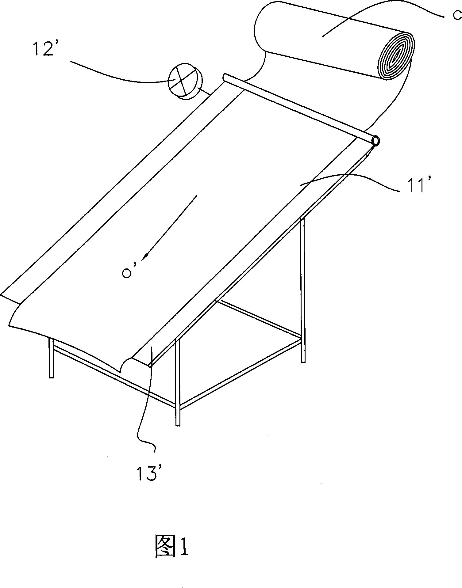
A technology of inspection device and inspection method, which is applied to the inspection of textile materials, material inspection products, and analysis of materials, etc., which can solve the problem of increased loss rate in garment processing, the inability to accurately know the 11' flawed block cloth on the cloth surface, and the inability to Mark the defects of the horizontal position of the cloth surface and other problems

Inactive Publication Date: 2008-01-23
陈明泽
View PDF1 Cites 13 Cited by
  • Summary
  • Abstract
  • Description
  • Claims
  • Application Information

AI Technical Summary

Problems solved by technology

[0002] The commonly used cloth inspection machine 1' is only equipped with a meter 12', as shown in Figure 1, the inspected cloth C is driven by a motor to record the cloth surface defects at the longitudinal length of the code table, and the inspected cloth C is working It is not possible to quantitatively send out the direction 0' for inspection on the table 13', and it is also impossible to mark the flaws in the horizontal position of the fabric surface 11', so we can only understand the flaws caused by the length (yardage) of the fabric surface, and there is another inspection machine with a traditional type The stopwatch (length me

Method used


Image

  • Checking device and method for continuous materials
  • Checking device and method for continuous materials
  • Checking device and method for continuous materials

Examples


Embodiment 1

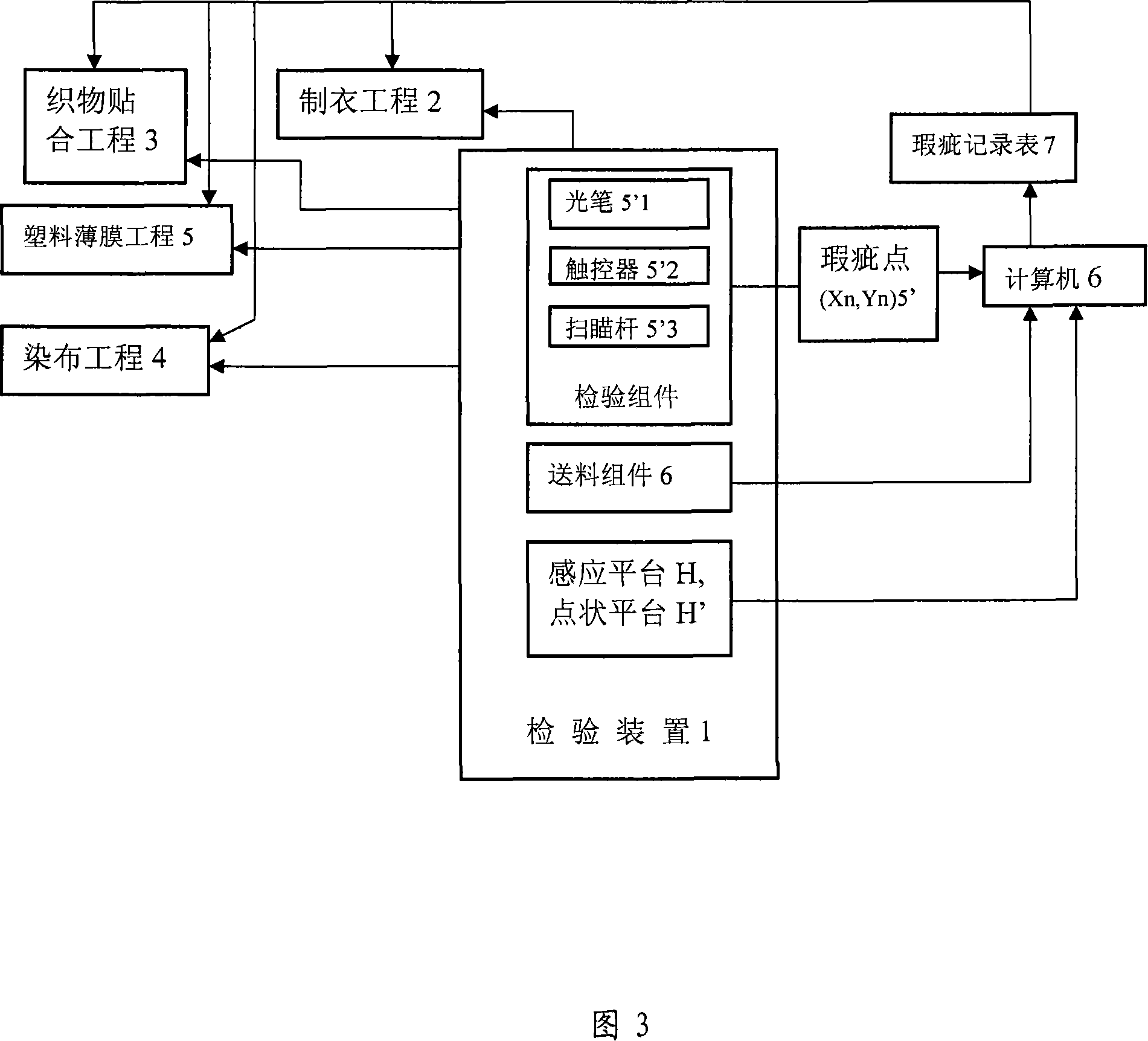
[0043] Take a batch of cloth (PL0001) and install it on the inspection device 1 with the feeding component for inspection. The PL0001 cloth is sent out by the feeding component in a fixed-length 1 / 4 yard for inspection, and is inspected by the touch sensor platform. For the defective part of the cloth, the coordinates of the defective points will be sent to the computer screen and some defective point A coordinates (30, 175), defective point B coordinates (75, 225), defective point C coordinates (60, 300 ), the defect point D coordinates (90, 350) as shown in Figure 7, the table is as follows:

[0044] Coordinate unit (yard, centimeter)

[0045]

[0046] 200

[0047] As mentioned above, according to the position of the defect point displayed on the screen E of the computer 6, the fabric defect record table is made and can be sent to the downstream processing industry.

Embodiment 2

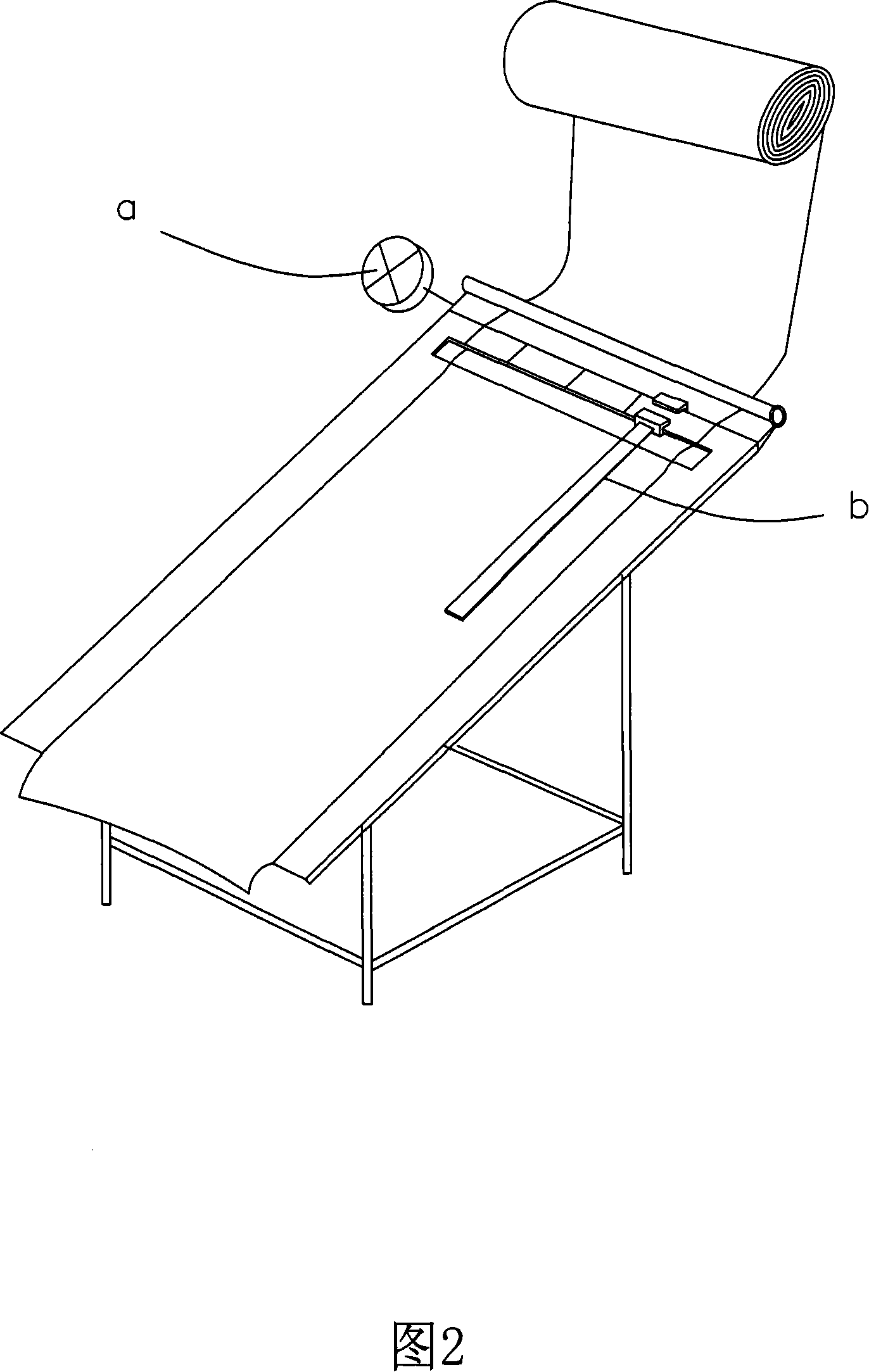
[0049]Take a batch of plastic cloth (FL0001), 25μ thickness, 60m / min line speed, and produce it under the conditions of coiling and inspection device 1 equipped with a feeding assembly. Control the fixed length to be inspected, and press the point-shaped platform with a light pen to inspect the defective part of the plastic cloth, and the coordinates of the defective points will be sent to the screen E of the computer 6 and the coordinates of some defective points a (15, 160), defect point b coordinates (60, 190) and defect point c coordinates (90, 230) are listed in the following table:

[0050] Coordinate unit (yard, centimeter)

[0051]

[0052] As mentioned above, according to the position of the defect point displayed on the screen E of the computer 6, a plastic cloth defect record table is made and can be sent to the downstream processing industry.


PUM


Abstract

The invention discloses a method and device for detecting materials continuously, which is presented for solving the problem associated with prior technology that it is impossible to carry out accurate detection. The device comprises a sensing platform or a spot platform, a feeding assembly and an inspection assembly. The detecting method in the invention comprises the following: the feeding assembly feeds the material to be detected continuously; the inspection assembly looks for the coordinate of any defective point (Xn, Yn) by a triggering or scanning way; the defective point (Xn, Yn) is displayed in a computer, a defective-point table makes record; the records in the defective-point table are sent to different processing stations. The invention can accurately mark the defective point (Xn, Yn) in a fabric by a light pen, trigger or scanning rod in conjunction with a sensing platform or a spot platform, is good for processing in the downstream, and can reduce loss and processing procedure.

Description

technical field [0001] The invention relates to a continuous material inspection device and its method, especially the combination of the improved inspection device equipped with a feeding assembly, an induction platform (or point platform), and an inspection assembly, and connected to a computer for continuous inspection. The method of materials is beneficial to the subsequent processing to reduce the loss rate and improve the efficiency. Background technique [0002] The commonly used cloth inspection machine 1' is only equipped with a meter 12', as shown in Figure 1, the inspected cloth C is driven by a motor to record the cloth surface defects at the longitudinal length of the code table, and the inspected cloth C is working It is not possible to quantitatively send out the direction 0' for inspection on the table 13', and it is also impossible to mark the flaws in the horizontal position of the fabric surface 11', so we can only understand the flaws caused by the length...

Claims


Application Information

Patent Timeline
IPC IPC(8): G01N21/892G01N33/36G01N35/00D06H3/00G01B11/03
Inventor 陈明泽
Owner 陈明泽
Why Eureka
Try Eureka