Control Area Network Machine Diagostic

a control area and network machine technology, applied in the field of rotating machinery, can solve the problems of failure or inefficiency of rotating machinery operation, limited capacity, and device inability to continuously measure the vibration of all connected sensors, and achieve the effect of high degree of accuracy and underestimate the magnitude of the resultant signal

Inactive Publication Date: 2017-03-09
DYTRAN INSTR +1
View PDF9 Cites 20 Cited by
  • Summary
  • Abstract
  • Description
  • Claims
  • Application Information

AI Technical Summary

Benefits of technology

[0011]Further, the present invention can more precisely process the vibration data because the tachometer data is sent directly to the bus-based smart vibration sensor without danger of collisions with other data on the bus.
[0012]An important vibration signal process using the tachometer involves a process called Time Synchronous Averaging (TSA). For this process to work, each revolution of a gear or shaft of interest must be marked accurately in the vibration data stream. A high degree of accuracy is needed marking the beginning and end of each revolution or the averaging process will be degraded significantly and underestimate the magnitude of the resultant signal. The present invention allows for this accuracy and thus allows for the TSA process to be performed inside the bus-based smart vibration sensor.

Problems solved by technology

Vibration forces can result in failure or inefficient operation of rotating machinery.
The problem with these traditional systems is that they use a central data collection device with limited capacity such that the device cannot continuously measure the vibration from all the connected sensors continuously.
This process degrades the diagnostic processing capabilities and also slows down the performance of the system, delaying the time until the next series of acquisitions can be acquired.
As an alternative, if 24 Analog-to-Digital converters are used in lieu of a mux arrangement, then the expense and size of the central data collection device is often too costly and requires too much mounting volume, particularly in applications where the circuitry is imbedded.
These advanced sensors are just now becoming available making the central data collection device unnecessary.
The bus architecture of the prior art offers extremely low probability of undetected data corruption; however, it allows for collisions where lower priority messages need to be sent multiple times when interfering with higher priority messages.
This is very problematic for the high frequency tachometer data that is needed in the vibration signal processing.
The possibility for collisions and indeterminate timing, coupled with the slow speed of the bus, pose serious problems for putting the tachometer data on the vibration sensor bus.

Method used


Image

  • Control Area Network Machine Diagostic
  • Control Area Network Machine Diagostic
  • Control Area Network Machine Diagostic

Examples


Embodiment Construction

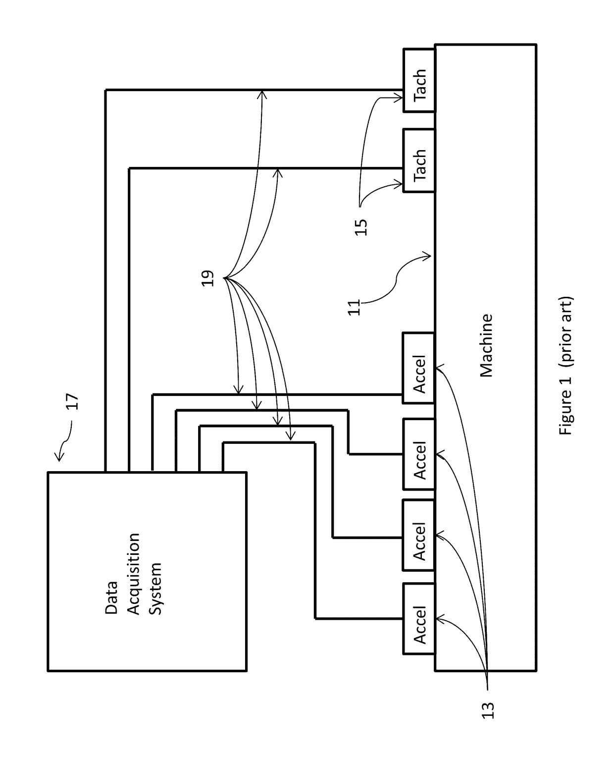
[0037]FIG. 1 is a schematic depiction of a typical traditional vibration monitoring system architecture where the output from machine 11 accelerometers 13 and tachometers 15 are wired directly to a central data acquisition system 17. It will be appreciated there may be as many accelerometers 13 and tachometers 15 as needed to gather the relevant data. The signals in the wires 19 are typically analog voltages which are processed in the central data acquisition system 17.

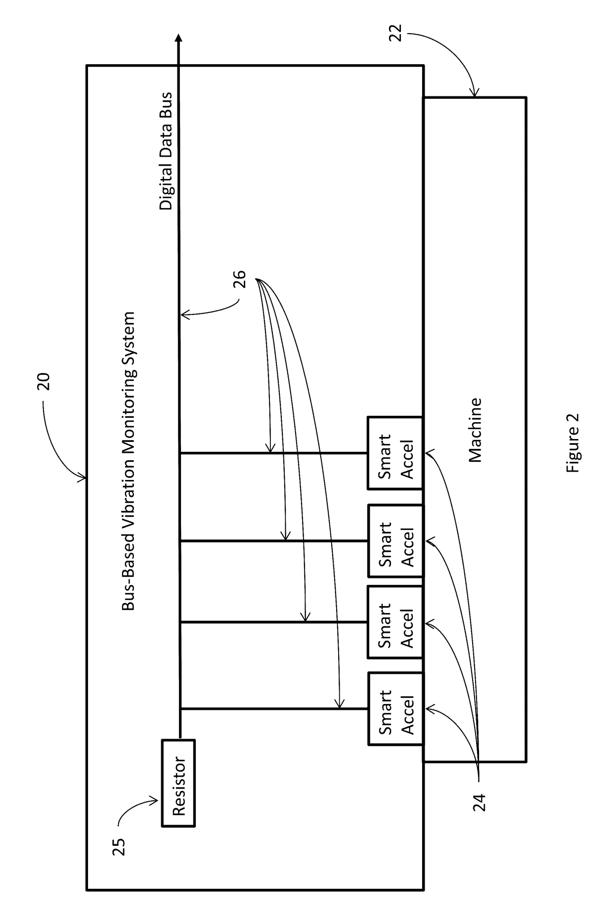
[0038]FIG. 2 is a schematic representation of a bus-based vibration monitoring system 20 of the present invention where the vibration data acquired from machine 22 is processed inside each vibration sensor 24. System 20 includes a 120 ohm bus resistor 25. The signals in the wires 26 are digital which includes vibration features related to any mechanical faults residing in the machine 22 at the time the signals are acquired.

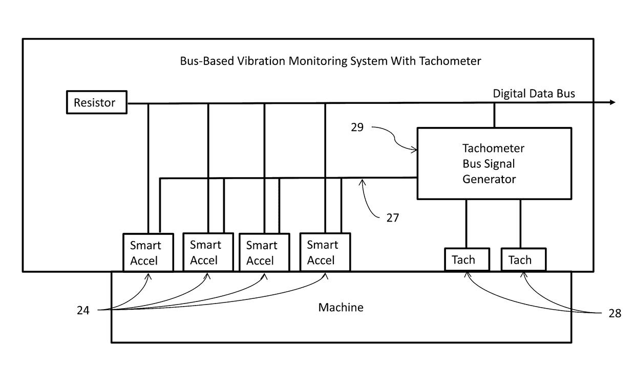
[0039]FIG. 3 shows how the signals from tachometers 28 are conditioned by bus-based signal condi...


PUM

PropertyMeasurementUnit
lengthsaaaaaaaaaa
frequenciesaaaaaaaaaa
speedsaaaaaaaaaa

Abstract

A method of monitoring and balancing rotary machinery utilizing bus-based smart vibration sensors with dedicated tachometer signals fed, via a wire or wirelessly, to each bus-based smart vibration sensor.

Description

BACKGROUND OF THE INVENTION[0001]The invention generally relates to rotating machinery and more particularly to a method and apparatus for using a bus-based smart vibration sensor in conjunction with a composite tachometer.[0002]Vibration forces can result in failure or inefficient operation of rotating machinery. To avoid such pitfalls, techniques and equipment have been developed to monitor and indicate when faults such as imbalance, bearing wear, gear wear, and other such faults are present. Reliable vibration monitoring systems typically begin with an accelerometer. This device is attached to the machine and creates an electrical output signal that is an analog representation of the vibration. The analog signal is typically a complex waveform with all the frequencies of each vibrating component mixed together.[0003]To aid in the decoding of this complicated vibration signal, a tachometer is usually used. The tachometer signal is generated using magnetic, optical, and various spe...

Claims


Application Information

Patent Timeline
Patent Type & Authority Applications(United States)
IPC IPC(8): G01N29/46G01P3/00
CPCG01N29/46G01N2291/0289G01P3/00F16C2233/00G01M7/00G01M13/028G01N29/14G01N29/2481G01N29/4472G01P3/481
Inventor GRABILL, PAULVARAK, DENIS
Owner DYTRAN INSTR
Why Eureka
Try Eureka