Device for chip removing machining

a technology for removing machining and chip, which is applied in the direction of shaping cutters, manufacturing tools, cutting inserts, etc., can solve the problems of shim plates that are relatively bulky, occupy a limited tool, and may be relatively bulky, so as to achieve the effect of facilitating workpieces and reducing the size of shim plates

Inactive Publication Date: 2017-06-06
SANDVIK INTELLECTUAL PROPERTY AB
View PDF21 Cites 0 Cited by
  • Summary
  • Abstract
  • Description
  • Claims
  • Application Information

AI Technical Summary

Benefits of technology

[0005]Thus, one aspect of the present embodiment is to provide an improved cutting tool for the chip removing machining of a workpiece, for instance a workpiece of titanium, steel, aluminium, castings, or another material.
[0033]The device according to the present embodiment is in particular advantageous and efficient for workpieces of metal or metal compositions, such as titanium, steel, aluminium, and castings. The device may, however, be used for other materials.

Problems solved by technology

In certain cases there may be problems with shim plates according to prior art, e.g. for smaller tools or for tools the body of which is provided with many cutting inserts in the direction of rotation and / or in the axial direction, whereby the shim plates may be relatively bulky and constitute a limitation for the tool.
Moreover, shim plates may be relatively bulky for tools having a body provided with many cutting inserts in the direction of rotation and accordingly have small distances between the cutting inserts (high tooth density) in the direction of rotation.

Method used


Image

  • Device for chip removing machining
  • Device for chip removing machining
  • Device for chip removing machining

Examples


first embodiment

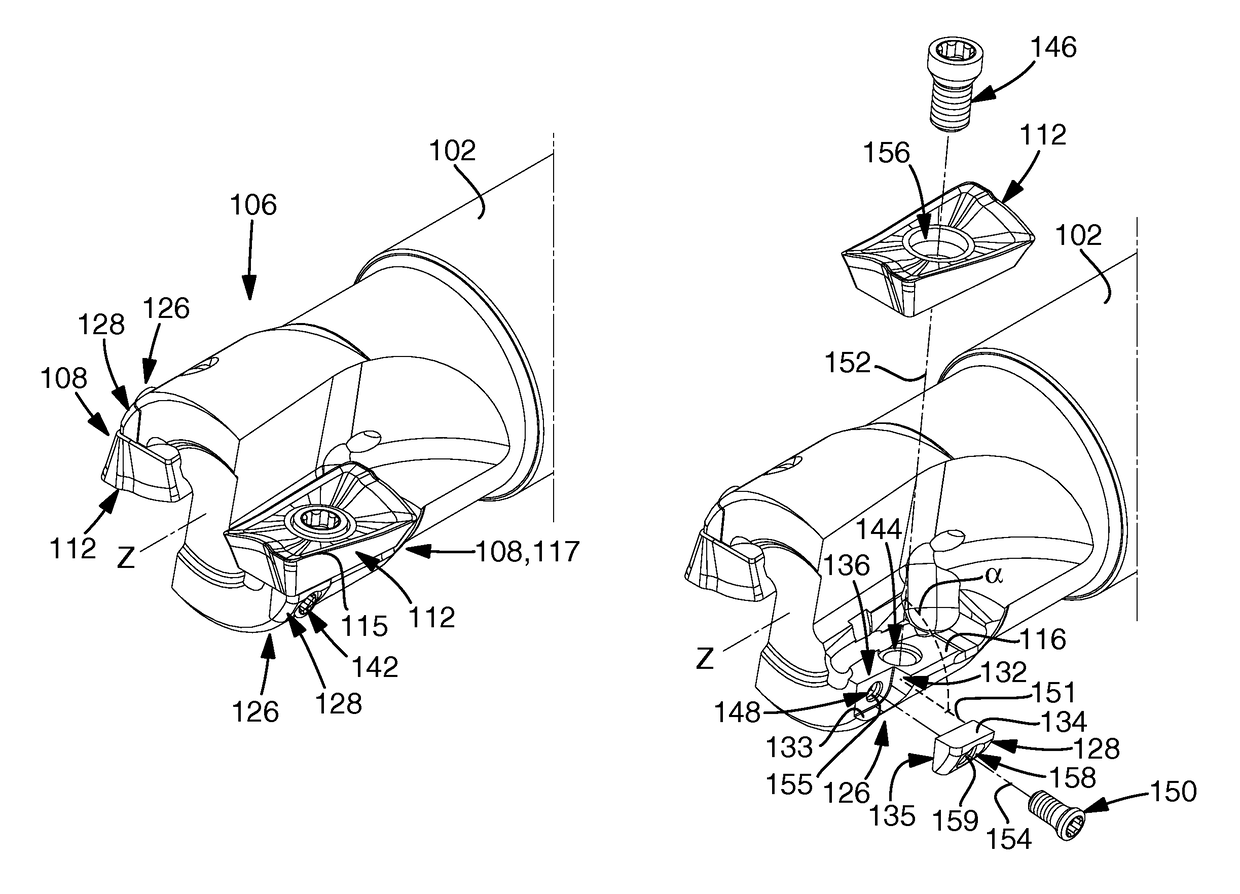
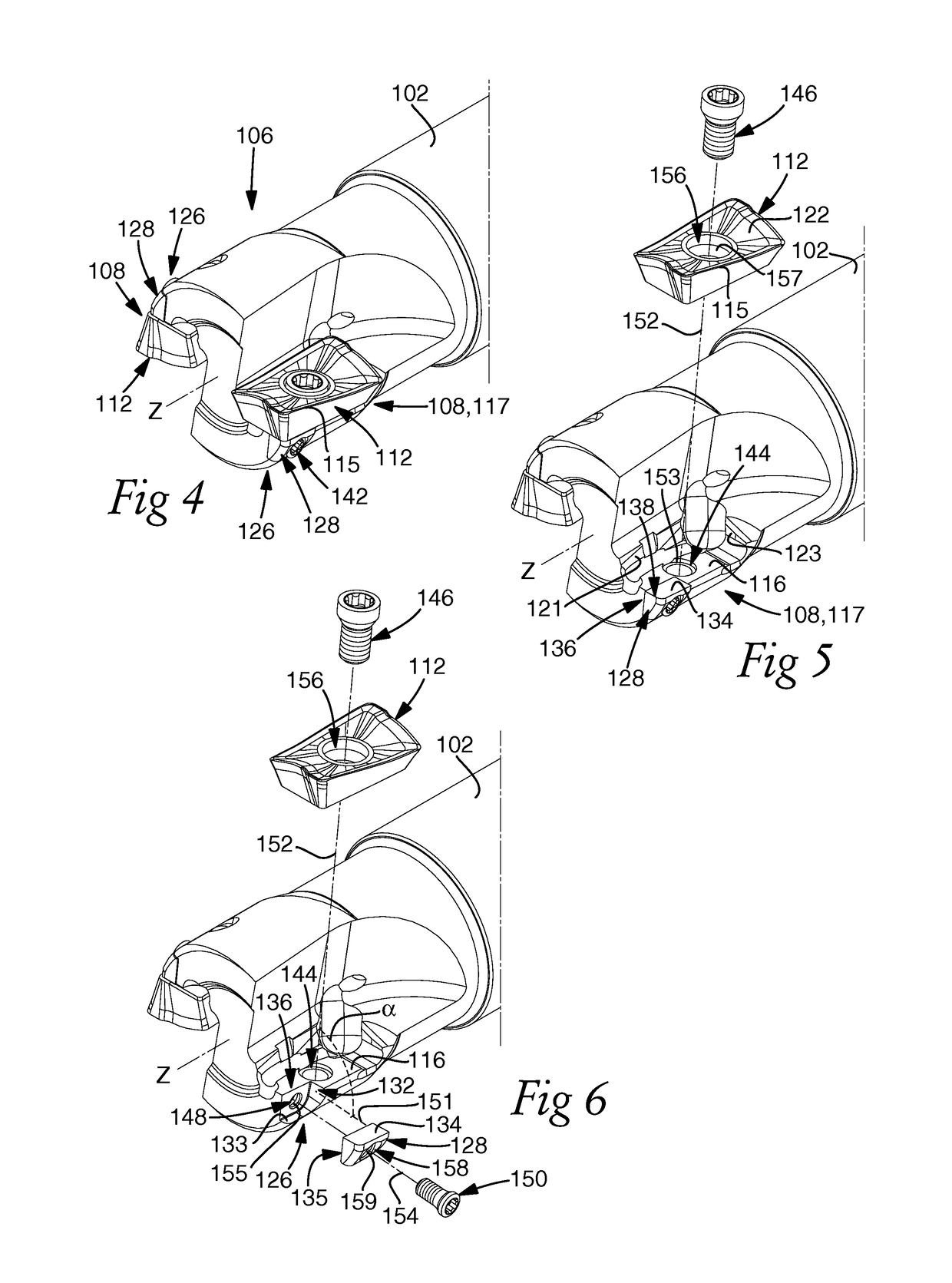
[0070]The device includes first mounting members 140 for the mounting of the cutting insert 112 and second mounting members 142 separated from first mounting members 140 and arranged for the mounting of the shim member 128. The respective mounting members 140, 142 may also be defined as mounting equipment. First mounting members 140 have a first recess 144 arranged in the body 102 and situated at the first seat 108 and that is arranged to receive and hold a first fastening element 146. Second mounting members 142 include a second recess 148 arranged in the body 102 and situated at the second seat 126 and that is arranged to receive and hold a second fastening element 150. The first recess 144 may define a first center axis 152 and the second recess 148 may define a second center axis 154. The first and second recess 144, 148 may be arranged in the body 102 in such a way that the first center axis 152 of the first recess 144 is displaced from the second center axis 154 of the second ...

second embodiment

[0073]With reference to FIG. 13, the respective first seat 108 of the second embodiment includes at least one location surface 221, 223 arranged to position the cutting insert 112 axially and radially in the active part 217 of the first seat 208, as described above adjacent to FIG. 5. At the second end portion 206, the body 202 is provided with the at least one first seat 208. The respective first seat 208 may open axially in the direction away from the first end portion 204 of the body 202 in relation to the center axis z-z of the body. The respective first seat 208 may open radially outward from the body 202 in relation to the center axis z-z of the body 202. The body 202 has a second seat 226 arranged for the receipt of a shim member 228, wherein the shim member 228 has at least one contact surface 234. The body 202 includes a second seat 226 for each first seat 208. The second seat 226 may adjoin the first seat 208.

[0074]The at least one first seat surface 216 may have a first r...


PUM


Abstract

A device for the chip removing machining of a work piece includes a body connectable to a holder or rotatable spindle. The body has at least one first seat to receive a cutting insert having a main cutting edge. The first seat has an active part including at least one first seat surface. The body receives the cutting insert in the first seat, the first seat including at least one location surface. The at least one location surface forms an angle with the first seat surface and positions the cutting insert axially and radially in the active part. The body has a second seat to receive a shim member such that the cutting insert adjoins the at least one first seat surface and the shim member. The cutting insert covers an area defined by the shim member and the at least one first seat surface.

Description

RELATED APPLICATION DATA[0001]This application claims priority under 35 U.S.C. §119 to SE Patent Application No. 1350146-5, filed on Feb. 6, 2013, which the entirety thereof is incorporated herein by reference.TECHNICAL FIELD[0002]The present embodiments relate to a device for the chip removing machining of a workpiece, for instance a workpiece of titanium, steel, aluminium, castings, or another material. The device includes a body that is connectable to a holder or a rotatable spindle. The body defines a center axis and includes at least a first seat arranged to receive a cutting insert having at least one main cutting edge arranged to be active during chip removing machining. The first seat has an active part including at least one first seat surface, the body being arranged to receive the cutting insert in the first seat against the at least one first seat surface. The body has a second seat arranged to receive a shim member, and the body is arranged to receive the shim member in...

Claims


Application Information

Patent Timeline
Patent Type & Authority Patents(United States)
IPC IPC(8): B23C5/22B23C5/10B23B27/16B23C5/06
CPCB23C5/06B23C5/109B23B2205/12B23B2205/16B23C2210/166B23C2210/168Y10T407/192Y10T407/2272B23C5/2298B23B27/164B23C5/2239
Inventor ROMAN, STEFAN
Owner SANDVIK INTELLECTUAL PROPERTY AB
Why Eureka
Try Eureka