Pump device and method therefor of conveying fluid, and method of manufacturing the pump device

a pump device and fluid technology, applied in the direction of piston pumps, positive displacement liquid engines, liquid fuel engines, etc., can solve the problems of negative impact on the delivery accuracy of pumps, and achieve the effect of achieving advantages and efficient results

Inactive Publication Date: 2019-01-22
SMITHS MEDICAL ASD INC
View PDF46 Cites 0 Cited by
  • Summary
  • Abstract
  • Description
  • Claims
  • Application Information

AI Technical Summary

Benefits of technology

[0009]The manufacturing of the housing of the pump device of the instant invention may be advantageously and efficiently achieved by coupling together two housing half portions with to be mated track portions preformed therein.

Problems solved by technology

For IV pumps that rely on an elastomeric member such as a tubing, the delivery accuracy of the pump may negatively impacted by external factors such as system back pressure and fluid viscosity.

Method used


Image

  • Pump device and method therefor of conveying fluid, and method of manufacturing the pump device
  • Pump device and method therefor of conveying fluid, and method of manufacturing the pump device
  • Pump device and method therefor of conveying fluid, and method of manufacturing the pump device

Examples


Embodiment Construction

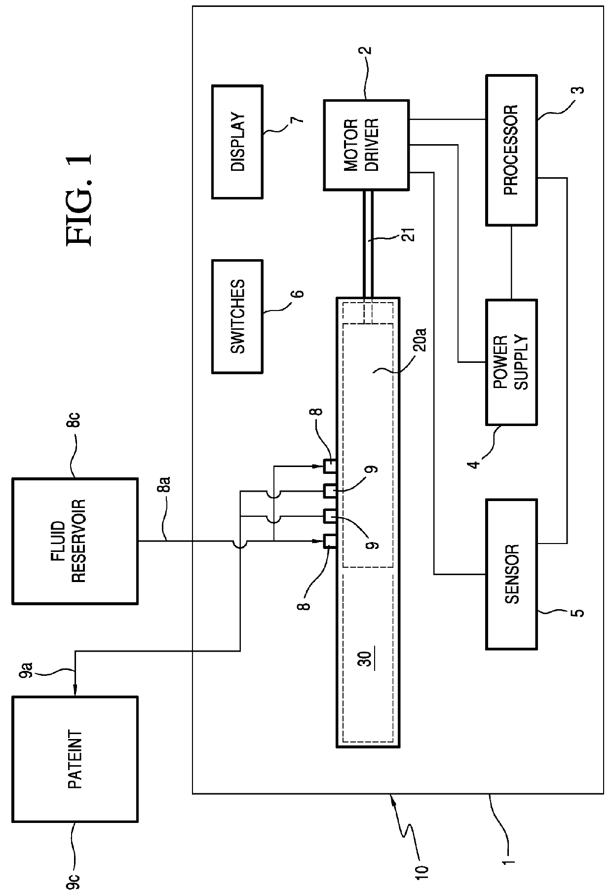
[0025]With reference to FIG. 1, the pump assembly 1 of the instant invention has an inventive pump 10 that includes a housing 30 and a piston 20a movably fitted to the housing. A drive shaft 21 connects piston 20a to a motorized driver 2 so that piston 20a is adapted to be driven bi-directionally by driver 2. Pump assembly 1 further includes a processor 3, a power supply 4 that may be battery powered or connectable directly to a power outlet as is well known, and a number of sensors 5 conventionally used to detect, among other things, the operation of driver 2, the speed with which the piston 20a is driven, and possible air bubbles in the fluid being pumped out to the patient. There are also provided in pump assembly 1 switches 6 for programming the operation of the pump and at least one display 7 to present information to the user as is conventionally known. The switches may not be separately provided if a touchscreen is used.

[0026]Housing 30 of pump 10 in FIG. 1 is shown to have m...


PUM


Abstract

A pump has a housing having at least one inlet, one outlet, and an internal track with a given configuration. A piston movably positioned inside the housing has at least one protuberance movably mated to the track. As the piston is reciprocally driven by a motor, it is guided by the movement of the protuberance along the track to move bidirectionally along the housing and selectively rotate such that when the piston is moved to a first position, a fluid path is established through the inlet to enable fluid to be input into the housing. When the piston is moved to a second position, another fluid path is established through the outlet so that fluid is output from the housing. Multiple chambers may be formed in the housing to enable synchronous and selective opening and closing of respective inlets and outlets to enhance fluid flow.

Description

CROSS-REFERENCE TO RELATED APPLICATION[0001]None.FIELD OF THE INVENTION[0002]This invention relates generally to pumps and pumping methods. More particularly, this invention relates to a novel pump, a method therefor of conveying a fluid between a fluid source and a fluid receiving device, and a process of manufacturing the pump.BACKGROUND OF THE INVENTION[0003]Many types of pumps are known in the art. These include, but are not limited to: elastomeric, peristaltic, syringe, reciprocating spool, and high flow rate pumps. The high flow rate pumps, often referred to as large volume delivery pumps, are used in the medical device field. For IV pumps that rely on an elastomeric member such as a tubing, the delivery accuracy of the pump may negatively impacted by external factors such as system back pressure and fluid viscosity.[0004]It is therefore desirable to have a pump that does not suffer from back pressure and viscosity deficits that current peristaltic pumps suffer, and advantageo...

Claims


Application Information

Patent Timeline
Patent Type & Authority Patents(United States)
IPC IPC(8): F04B1/12F04B53/14F04B53/16F04B39/00F04B9/04F04B13/00
CPCF04B9/047F04B1/124F04B53/162F04B39/0005F04B53/14F04B13/00
Inventor ADAMS, GRANT
Owner SMITHS MEDICAL ASD INC
Why Eureka
Try Eureka